Porous Media Flow Module Updates
For users of the Porous Media Flow Module, COMSOL Multiphysics® version 5.6 brings a new Layered Darcy's Law interface, new interfaces and features for modeling heat and moisture transport in porous media, and revamped features for the existing Transport of Diluted Species and Heat Transfer in Porous Media interfaces. Learn more about the updates below.
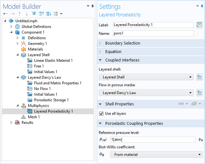
Poroelasticity, Layered Shell Multiphysics Interface
The new Poroelasticity, Layered Shell multiphysics interface enables modeling of multilayered domains (paperboards, composites, etc.) having different material properties per layer. The interface adds the Layered Shell and the new Layered Darcy’s Law interfaces, together with a new Layered Poroelasticity multiphysics node.
The new Layered Darcy’s Law interface, which is used in the above multiphysics interface, simulates the fluid flow through interstices in layered porous media, such as paperboards, composites, or plywood. You can model low-velocity flows and porous media flow where the permeability and porosity are very small, and for which the pressure gradient is the major driving force.
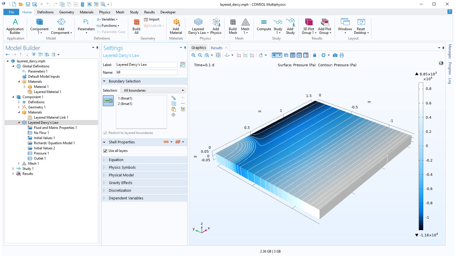
New Layered Darcy’s Law Interface
The new Layered Darcy’s Law interface can be used to simulate fluid flow through interstices in layered porous media, such as paperboard, composites, or plywood. You have the ability to model low-velocity flows and porous media flow where the permeability and porosity are very small and for which the pressure gradient is the major driving force.
Additionally, the new Poroelasticity, Layered Shell multiphysics interface allows the modeling of multilayer domains (paperboard, composites, etc.) having different material properties per layer. The interface adds the Layered Shell and the new Layered Darcy’s Law interfaces, together with the new Layered Poroelasticity multiphysics node. The Layered Shell interface requires the Composite Materials Module.
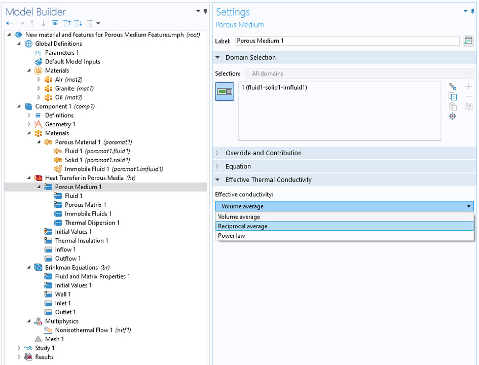
New Porous Medium Feature
A new feature for handling a porous medium is available for defining the different phases: solids, fluids, and immobile fluids. In the Heat Transfer in Porous Media interface, the Porous Medium feature is used to manage the material structure with a dedicated subfeature for each phase: Fluid, Porous Matrix, and optionally, Immobile Fluids. This new workflow provides added clarity and improves the user experience. It also facilitates multiphysics couplings in porous media in a more natural way. Combined with the Moisture Transport and Porous Media Flow interfaces, the heat transfer in porous media improvements enable the modeling of nonisothermal flow and latent heat storage in porous media.
You can see this new setup in the following models:
Heat and Moisture Transport in Porous Media
There are new interfaces and features for modeling coupled heat and moisture transport in porous media filled with moist air and liquid water. The new Moisture Transport in Porous Media interface provides a Hygroscopic Porous Medium feature by default, and can be used to model moisture transport in porous media by vapor convection and diffusion, as well as liquid water convection and capillary flow. The new interface accounts for convection in both liquid and gas phases due to total pressure variations, by modeling the liquid capillary flux, and by adding support for gravity forces. It can be combined with the Moist Air feature to model the effect of a moist air flow on a porous medium.
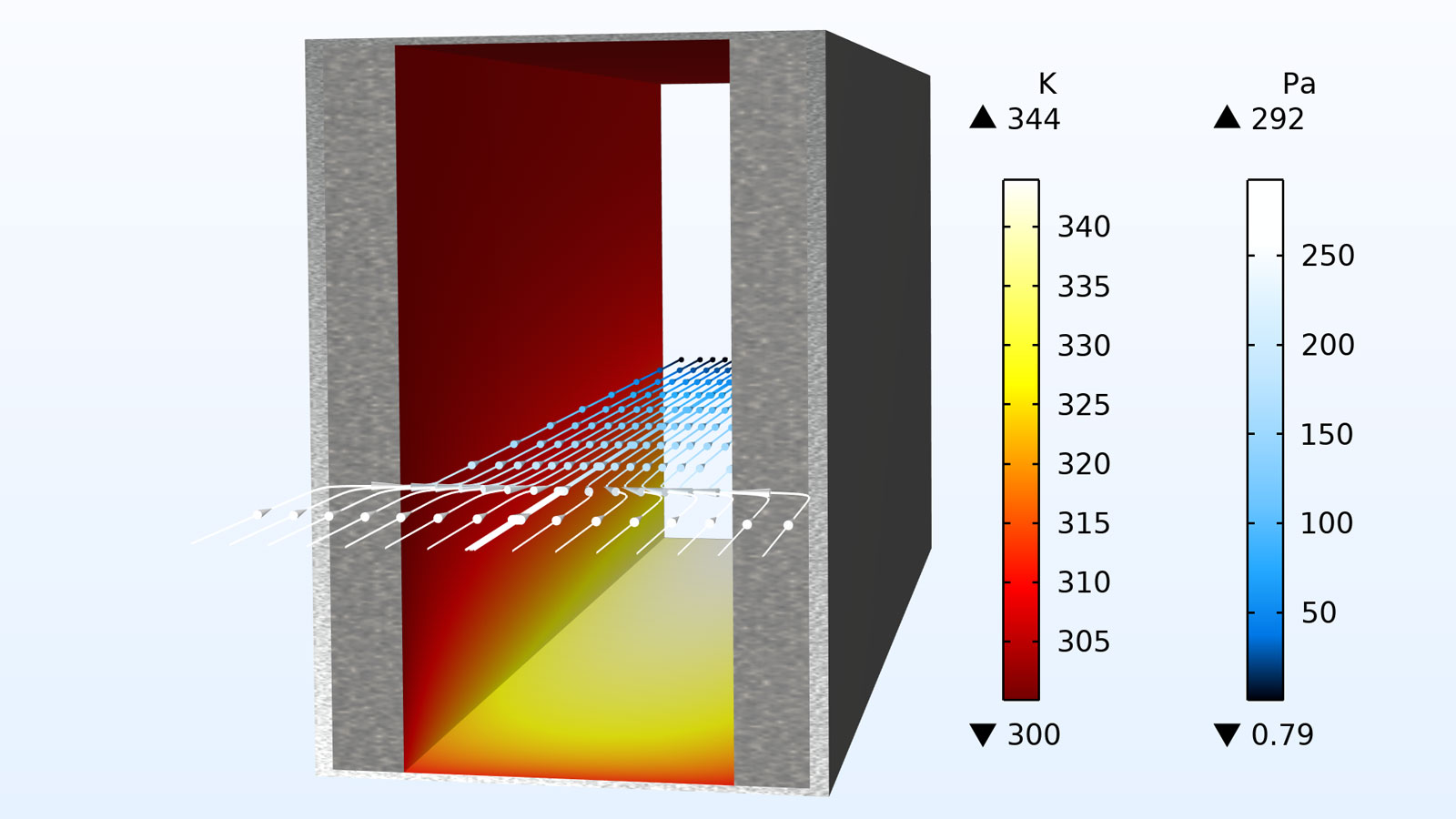
In the Heat Transfer interface, the new Moist Porous Medium domain feature defines effective material properties from the solid, liquid water, and moist air properties individually. The Moist Air subnode defines the material properties by taking into account the moisture content, and computes the convective flux and diffusive enthalpy flux in moist air. The Liquid Water subnode defines the liquid water saturation and velocity field, which may be automatically set by the Heat and Moisture multiphysics coupling, if available. The solid properties are handled by the Porous Matrix subnode. These new functionalities can be used for drying and evaporative cooling applications.
Revamped Porous Media Features for Transport of Diluted Species
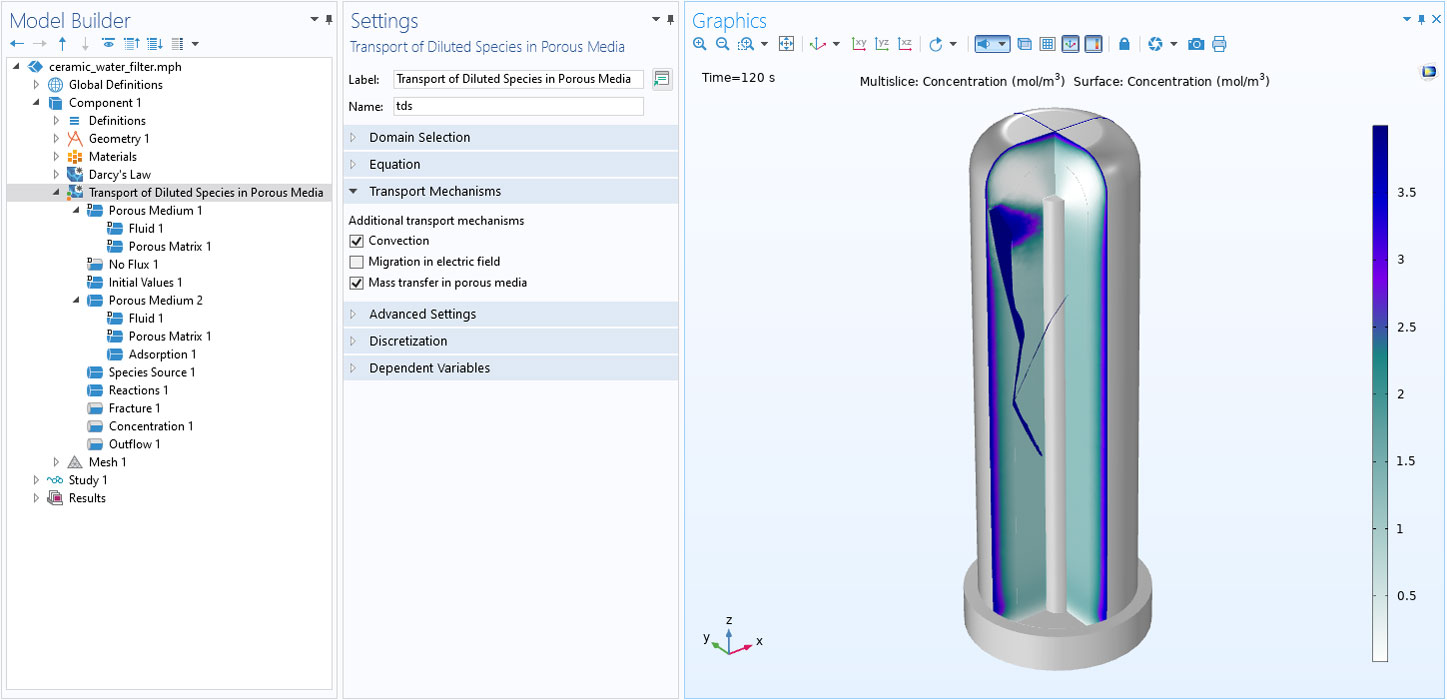
The Transport of Diluted Species in Porous Media interface is revamped to use the new Porous Medium node. Two new domain features, the Porous Medium and the Unsaturated Porous Medium nodes, are available in the Transport of Diluted Species in Porous Media interface. You can use the new Porous Medium node for assigning material properties to the multiple phases in a porous medium. The new nodes have dedicated containers to define the properties for the liquid, gas, and porous matrix. You can see this functionality demonstrated in the Ceramic Water Filter with Activated Carbon Core tutorial model.
Automatic Detection of Ideal Gas Material in Heat Transfer in Fluids
The Fluid feature, available within the various heat transfer interfaces, has been updated to take advantage of the ideal gas assumption to improve computational efficiency. The new From material option of the Fluid type list automatically detects whether the material applied on each domain selection is an ideal gas or not, and uses the relevant properties for either case. This may speed up computation when computing pressure work in compressible nonisothermal flows, for example. Since the gases available in COMSOL Multiphysics® and in the Material Library are modeled as ideal gases, many models with compressible nonisothermal flow are expected to benefit from this improvement.

Phase Change Interface Boundary Condition
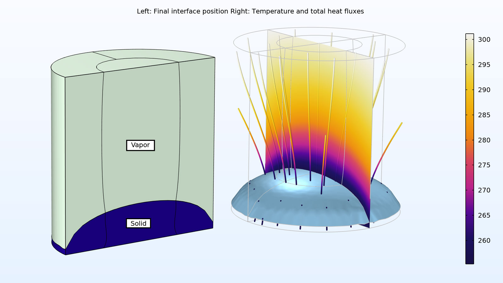
The new Phase Change Interface boundary condition, combined with the deformed geometry feature, defines the interface between two domains corresponding to two different phases. This boundary condition is based on the Stefan condition; it sets the phase change temperature, defines the front velocity from the latent heat of phase change, and specifies the solid side and heat flux jump evaluation. This boundary condition models the phase transformation as a sharp interface and can be used for a number of applications, including pure metal melting, as seen in the Tin Melting Front model, or solidification or sublimation, as seen in the Freeze-Drying model.
New Tutorial Models and Applications
COMSOL Multiphysics® version 5.6 brings new tutorial models to the Porous Media Flow Module.
Analyzing Porous Structures on the Microscopic Scale
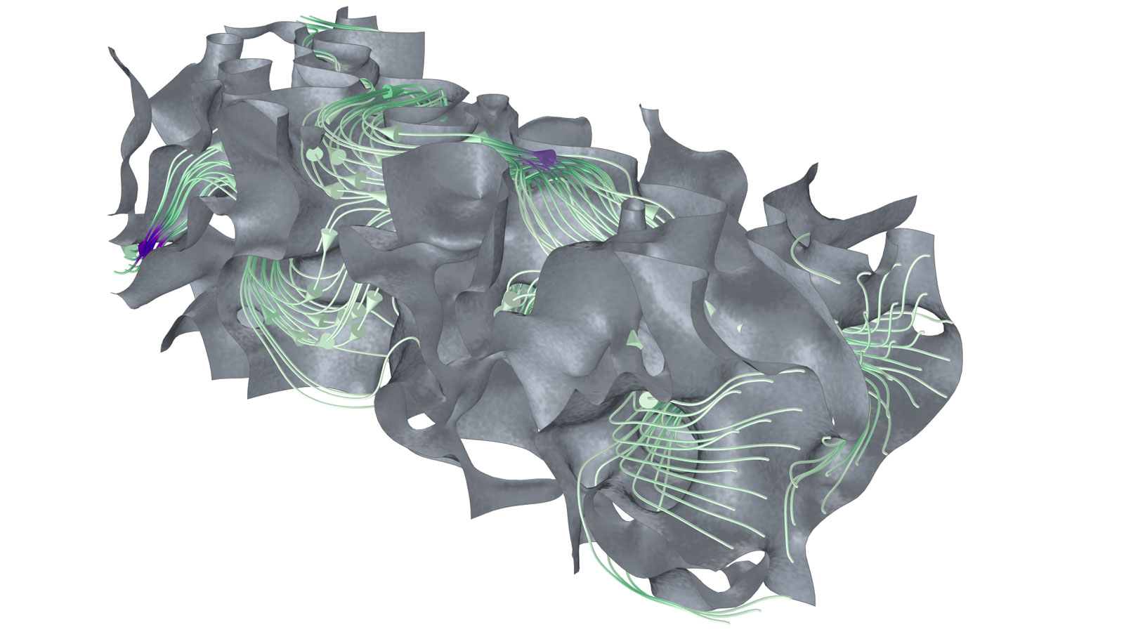
Application Library Title:
pore_scale_flow_3D
Optimization of a Porous Microchannel Heat Sink
Application Library Title:
porous_microchannel_heat_sink_optimization