Heat Transfer Module Updates
For users of the Heat Transfer Module, COMSOL Multiphysics® version 5.6 includes directional dependent surface properties for surface-to-surface radiation, a new Porous Medium feature, and a Phase Change Interface boundary condition. Read about these heat transfer features and more below.
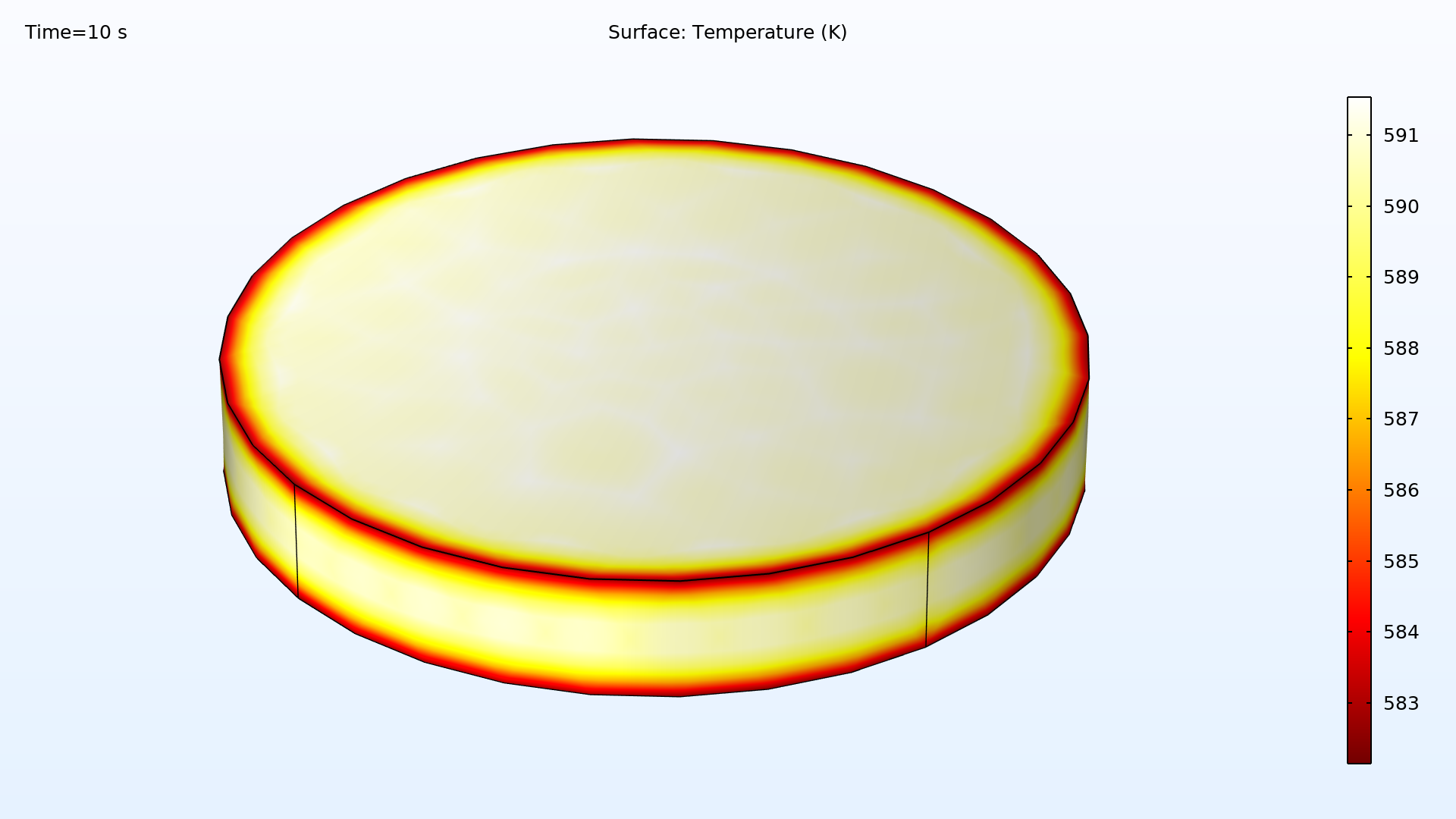
Phase Change Interface Boundary Condition
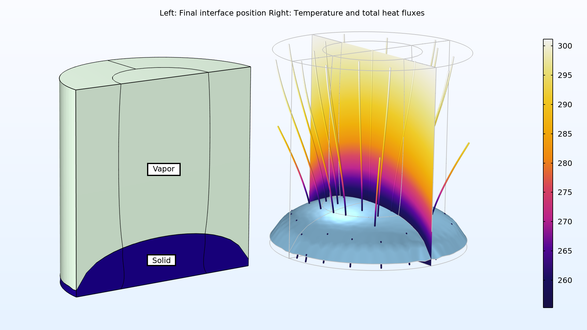
The new Phase Change Interface boundary condition, combined with the Deformed Geometry feature, defines the interface between two domains corresponding to two different phases. This boundary condition is based on the Stefan condition; it sets the phase change temperature, defines the front velocity from the latent heat of phase change, and specifies the solid side and heat flux jump evaluation. This boundary condition models the phase transformation as a sharp interface and can be used for a number of applications, including pure metal melting, as seen in the Tin Melting Front model, or solidification or sublimation, as seen in the Freeze-Drying model.
Heat and Moisture Transport in Porous Media
There are new interfaces and features for modeling coupled heat and moisture transport in porous media filled with moist air and liquid water. The new Moisture Transport in Porous Media interface provides a Hygroscopic Porous Medium feature by default, and can be used to model moisture transport in porous media by vapor convection and diffusion, as well as liquid water convection and capillary flow. The new interface accounts for convection in both liquid and gas phases due to total pressure variations, by modeling the liquid capillary flux, and by adding support for gravity forces. It can be combined with the Moist Air feature to model the effect of a moist air flow on a porous medium.
In the Heat Transfer interface, the new Moist Porous Medium domain feature defines effective material properties from the solid, liquid water, and moist air properties individually. The Moist Air subnode defines the material properties by taking into account the moisture content, and computes the convective flux and diffusive enthalpy flux in moist air. The Liquid Water subnode defines the liquid water saturation and velocity field, which may be automatically set by the Heat and Moisture multiphysics coupling, if available. The solid properties are handled by the Porous Matrix subnode. These new functionalities can be used for drying and evaporative cooling applications.

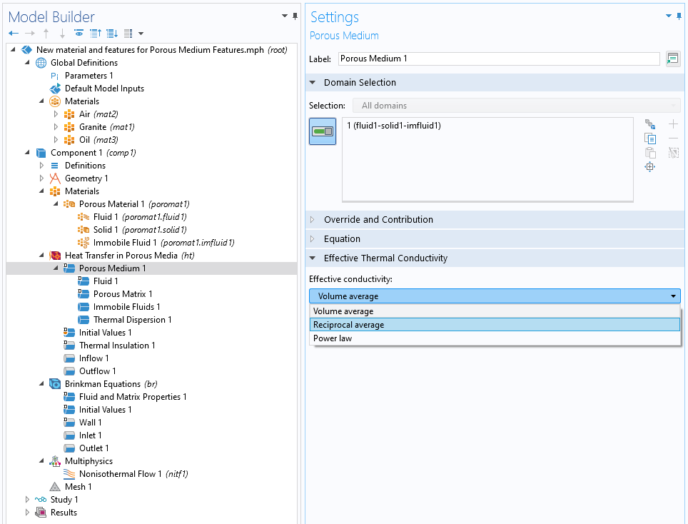
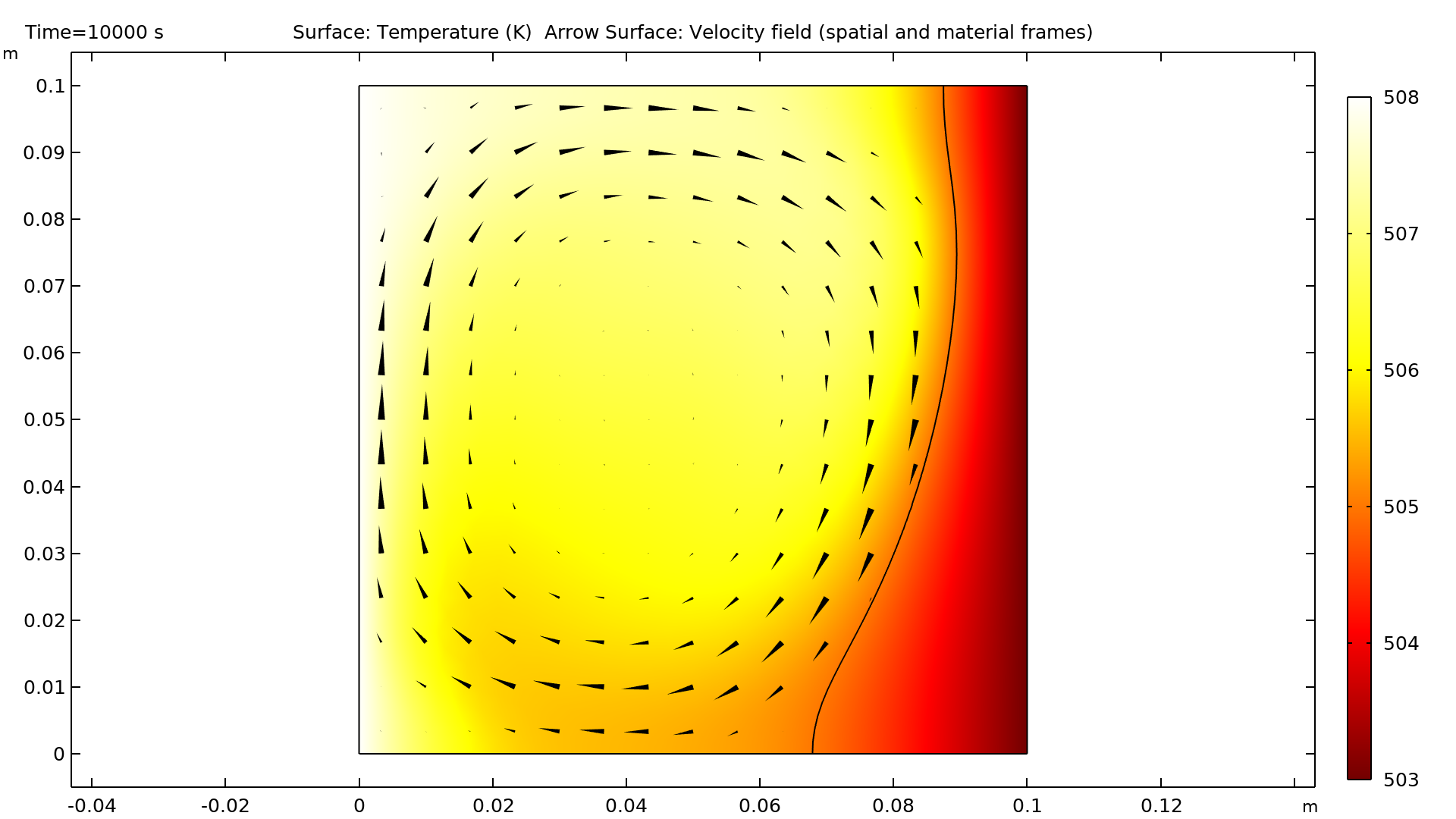
New Porous Medium Feature
A new feature for handling a porous medium is available for defining the different phases: solids, fluids, and immobile fluids. In the Heat Transfer in Porous Media interface, the Porous Medium feature is used to manage the material structure with a dedicated subfeature for each phase: Fluid, Porous Matrix, and optionally, Immobile Fluids. This new workflow provides added clarity and improves the user experience. It also facilitates multiphysics couplings in porous media in a more natural way. Combined with the Moisture Transport and Porous Media Flow interfaces, the heat transfer in porous media improvements enable the modeling of nonisothermal flow and latent heat storage in porous media.
You can see this new setup in the following models:
- heat_pipe
- frozen_inclusion
- evaporation_porous_media_large_rate
- porous_microchannel_heat_sink
- convection_porous_medium
- carbon_deposition
- monolith_3d
- steam_reformer
Directional Dependent Surface Properties for Surface-to-Surface Radiation
In the Surface-to-Surface Radiation interface, when the ray shooting method is selected, you can now define surface properties that depend on the radiation incidence angle. This is available in the Opaque Surface and Semitransparent Surface features for the surface emissivity, reflectivity, and transmittivity. This is useful for simulating surfaces that have a texture or pattern that is absorbing, reflecting, and transmitting heat radiation differently in different directions.

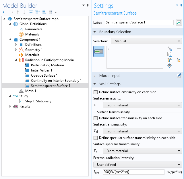
Semitransparent Surface for Radiation in Participating Media
The new Semitransparent Surface feature is available in the Radiation in Participating Media interface. On exterior boundaries, you can specify an external radiation intensity and account for the part of this incoming intensity that is diffusively or specularly transmitted through the surface. On interior boundaries, the radiation intensities on both sides of the surface are considered. This boundary condition is especially useful for modeling incident radiation coming from a transparent media on a participating media sample. This is the case for modeling the characterization of radiative properties of participating media, for example. You can see this feature demonstrated in the Radiative Cooling of a Glass Plate with Semitransparent Surfaces model.
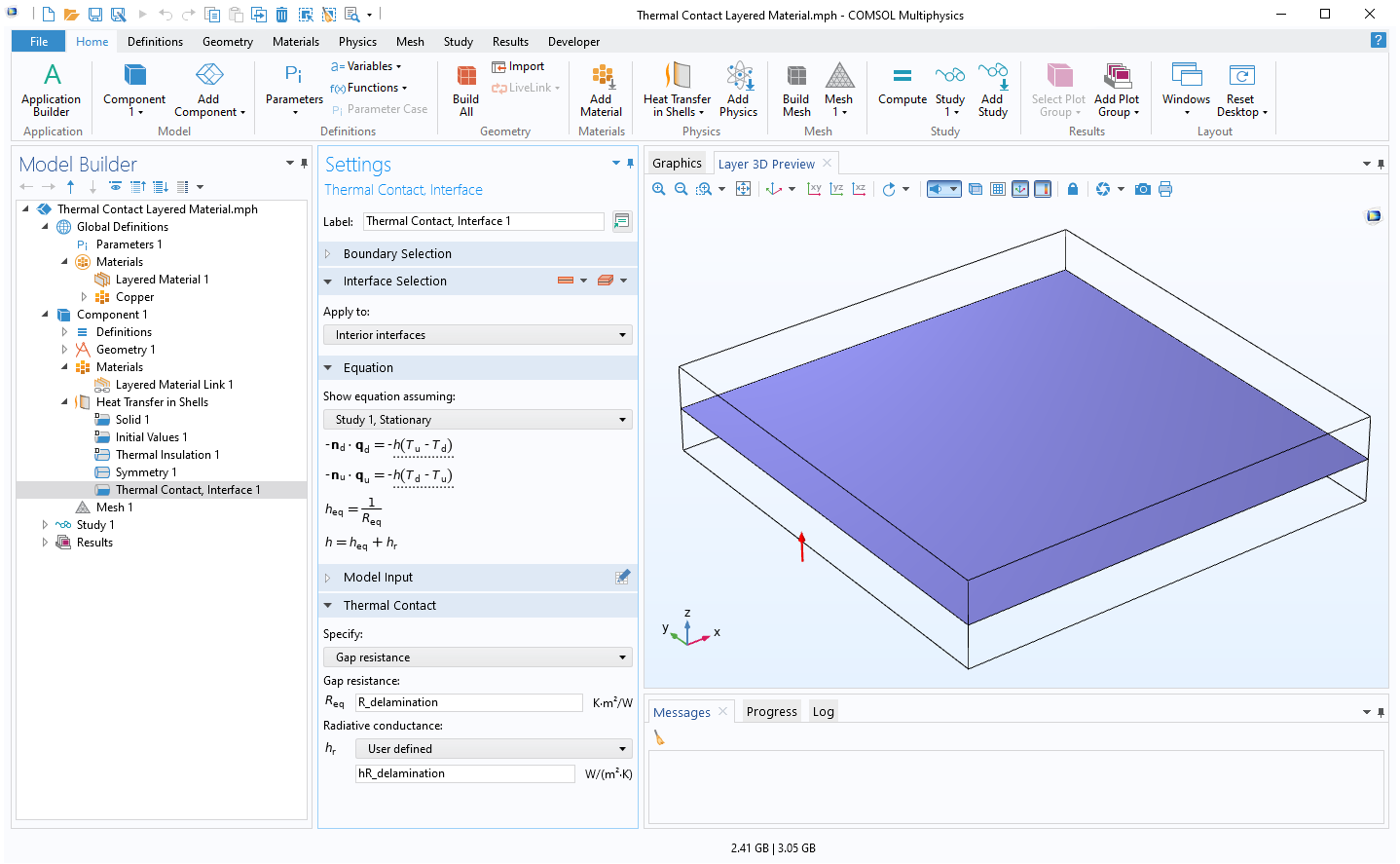
Thermal Contact and Symmetry for Layered Material
New functionalities extend the modeling capabilities for layered materials. The new Thermal Contact, Interface feature allows you to represent the surface asperities and the gap at the internal interfaces between the layers of a layered shell that are responsible for thermal resistance between the layer. This is needed to model the effect of delamination on thermal performances, as demonstrated in the Thermal Expansion of a Laminated Composite Shell with Thermal Contact, Interface model. Additionally, a Symmetry feature, introduced in the Heat Transfer in Shells interface, allows you to set symmetry conditions on edges to reduce the size of symmetric models.
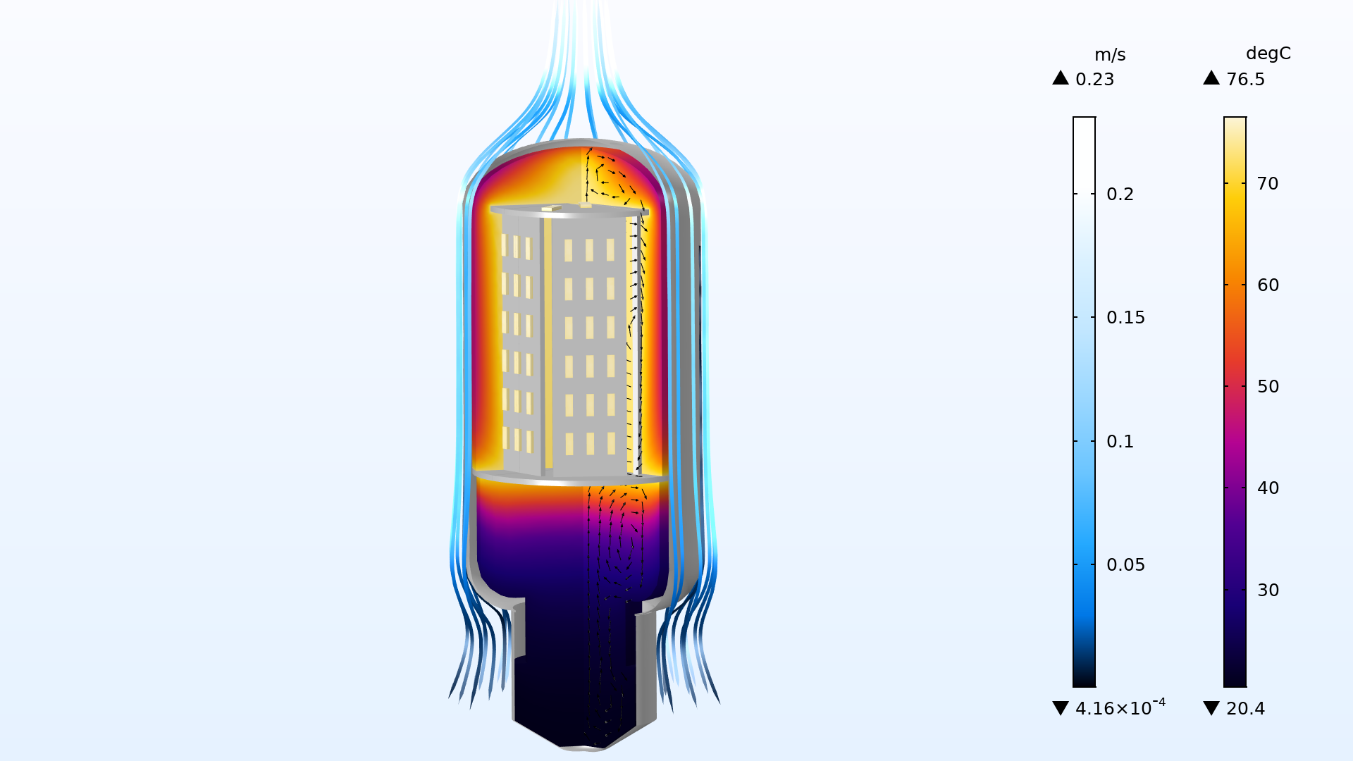
Automatic Detection of Ideal Gas Material in Heat Transfer in Fluids
The Fluid feature, available within the various heat transfer interfaces, has been updated to take advantage of the ideal gas assumption to improve computational efficiency. The new From material option of the Fluid type list automatically detects whether the material applied on each domain selection is an ideal gas or not, and uses the relevant properties for either case. This may speed up computation when computing pressure work in compressible nonisothermal flows, for example. Since the gases available in COMSOL Multiphysics® and in the Material Library are modeled as ideal gases, many models with compressible nonisothermal flow are expected to benefit from this improvement.
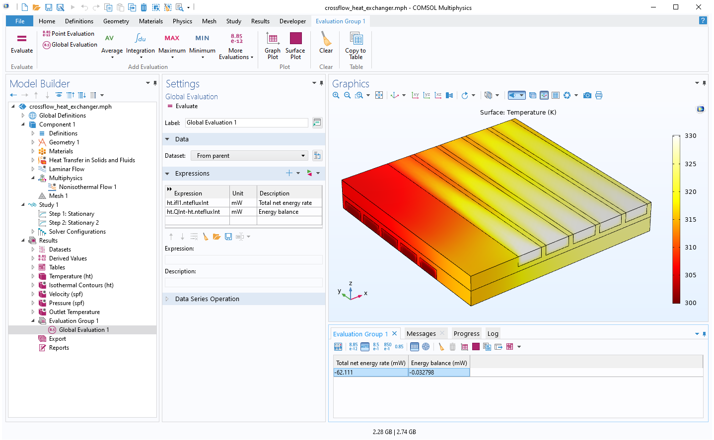
Heat and Energy Balance
The postprocessing variables for energy and heat balance definition have been extended to cover new configurations. Specifically, the variables are for nonisothermal flow, to account for out-of-plane heat sources; for the work of volume forces, viscous dissipation, and pressure; for boundary stresses; and for enthalpy flux in cases of nonzero normal velocity on internal walls. The postprocessing variables or energy and heat balance definition have also been extended to layered materials. Energy and heat balance provide an alternative criterion to the solver error estimate to check the simulation accuracy. You can see this functionality demonstrated in the Electronic Chip Cooling model.
New and Updated Tutorial Models and Applications
COMSOL Multiphysics® version 5.6 brings new and updated models and applications to the Heat Transfer Module.
Freeze Drying
Application Library Title:
freeze_drying
Download from the Application Gallery
Radiative Cooling of a Glass Plate with Semitransparent Surfaces
Application Library Title:
glass_plate_semitransparent_surface
Download from the Application Gallery
Tin Melting Front
Application Library Title:
tin_melting_front
Download from the Application Gallery
Evaporation in Porous Media with Large Evaporation Rates
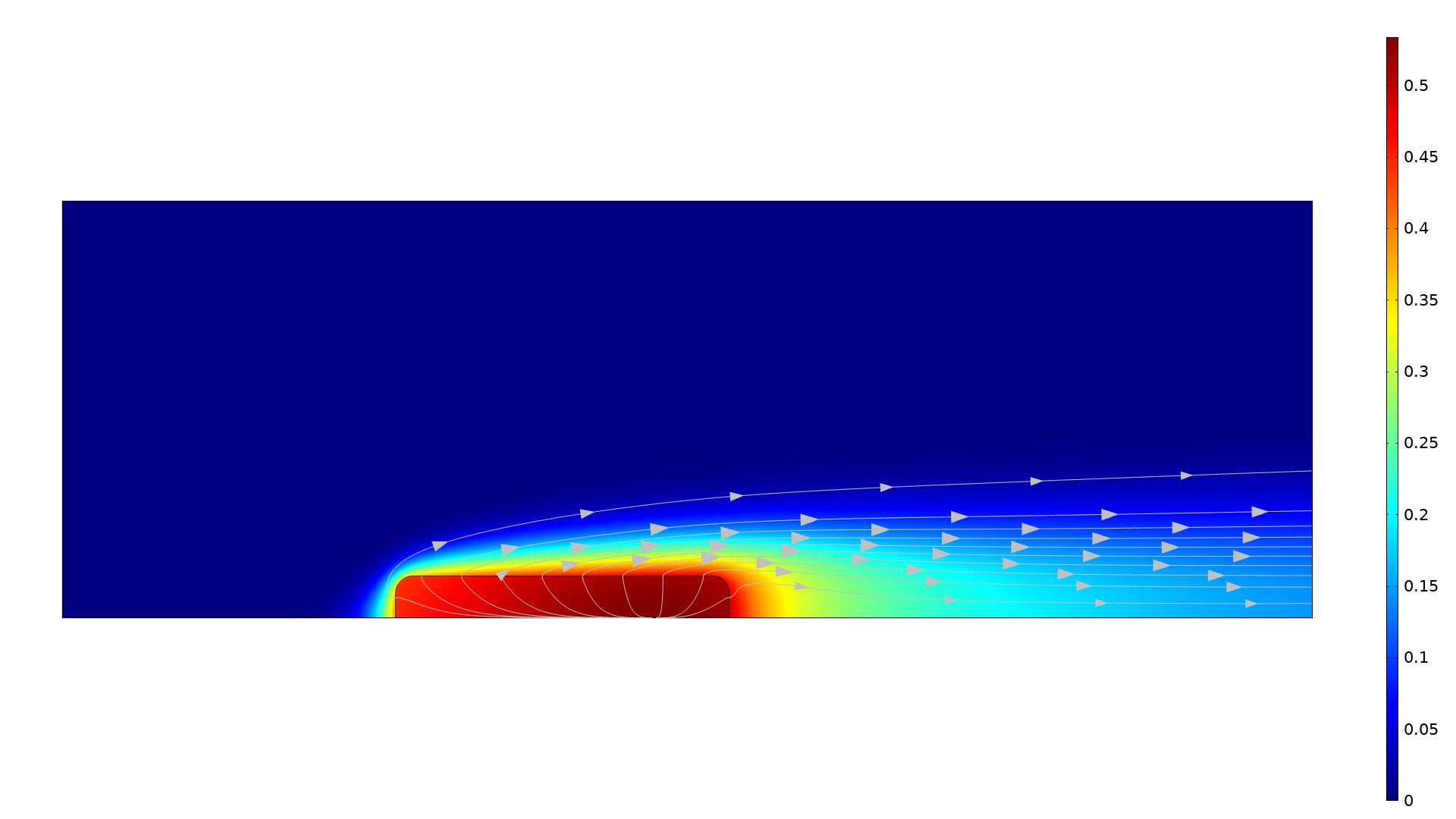
Application Library Title:
evaporation_porous_media_large_rate
Download from the Application Gallery
Inline Induction Heater
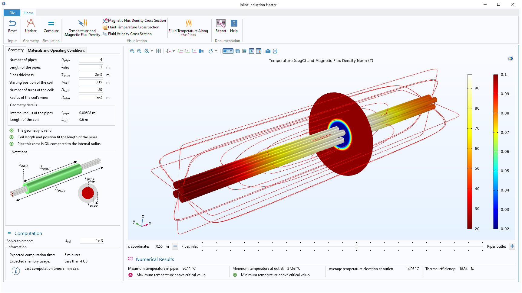
Application Library Title:
inline_induction_heater
Download from the Application Gallery