Design Module Updates
For users of the Design Module, COMSOL Multiphysics® version 5.6 includes more advanced Boolean operations and improvements to the constraints and dimensions functionality. Read about these improvements and more below.
Design Module Boolean Operations
The Design Module adds support for more advanced Boolean operations that can be enabled in the Geometry Settings window when working with a 3D model. Enabling these Boolean operations is expected to yield better results in more complex cases, for example, when computing the union of objects having touching faces that do not match exactly.
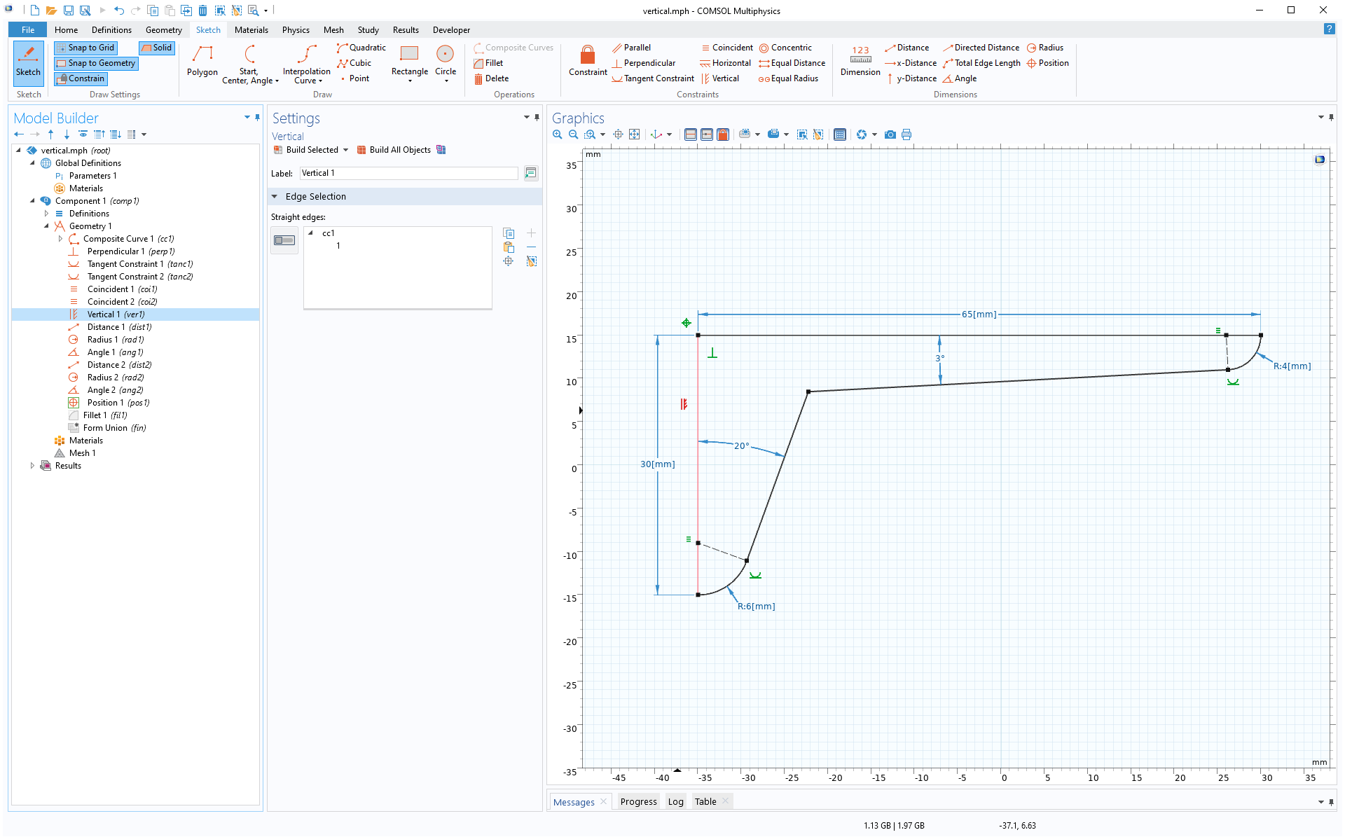
Horizontal and Vertical Constraints
The new Horizontal and Vertical constraints make it easier to constrain straight edges to be parallel to the x- and y-axes. Previously, the x-Distance and y-Distance dimensions, with the dimension value set to zero, were being applied to the end points of the edges to achieve the same constraint.
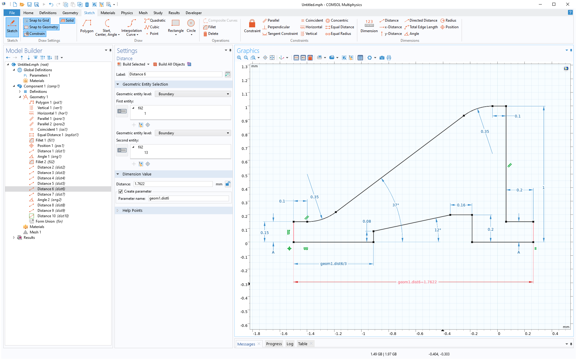
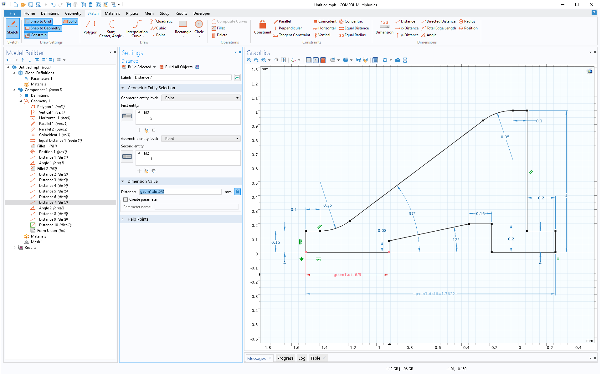
Measuring Dimensions and Dimension Parameters
Measuring dimensions have been introduced to add dimensions as a measurement, and do not constrain the geometry. To change a dimension into a measuring dimension, toggle the padlock icon to the right of the dimension value. You can also create a parameter from a dimension by selecting its Create parameter check box. The parameter can be used in geometry, mesh, and physics, for example, with some restrictions. When used in the expression of another 2D geometry feature, the expression must depend linearly on the parameter. Parameters can be created from both constraining and measuring dimensions.
Automatic Constraint Generation
The new Constrain button in the Sketch toolbar adds appropriate constraints automatically when drawing or dragging a vertex with the Snap to Geometry option turned on. For example, while drawing consecutive segments of a polygon that snap to being perpendicular, a Perpendicular constraint will be created automatically when the Constrain button is enabled.
Detect Interferences
The Detect Interferences tool, added to the Defeaturing and Repair menu, can detect interference between objects. This tool supports solid and surface objects as input and detects intersections, touches, gaps, and containments. You can see this feature demonstrated in the Creating a Fluid Domain Inside a Solid Structure tutorial model.

Check Feature
The new Check feature, added to the Defeaturing and Repair menu, can be used to detect faults in CAD objects. Add a Check node to a geometry sequence, such as after a Delete Faces operation, to confirm that no problems remain after replacing a faulty face.
No faults remain in this geometry after replacing the faulty face using the Delete Faces operation.
Support for New and Updated CAD File Format Versions
The CAD file import and export functionality has been extended to support new versions for the following file formats:
Read from File
- AutoCAD® (.dwg, .dxf): 2021
- PTC Creo Parametric™ (.prt, .asm): 7.0
- Inventor® (.ipt, .iam): 2021
- NX™ (.prt): 1899
- Parasolid® (.xt, .xb, .xmttxt, .xmtbin): 33.0
Write to File
- Parasolid® (.xt, .xb, .xmttxt, .xmtbin): 33.0
Autodesk, the Autodesk logo, AutoCAD, and Inventor are registered trademarks or trademarks of Autodesk, Inc., and/or its subsidiaries and/or affiliates in the USA and/or other countries. Parasolid and NX are trademarks or registered trademarks of Siemens Product Lifecycle Management Software Inc. or its subsidiaries in the United States and in other countries. PTC, Creo, and Creo Parametric are trademarks or registered trademarks of PTC Inc. or its subsidiaries in the U.S. and in other countries. COMSOL AB and its subsidiaries and products are not affiliated with, endorsed by, sponsored by, or supported by these third parties.