RF Module Updates
For users of the RF Module, COMSOL Multiphysics® version 5.6 introduces a new physics interface analyzing radar cross sections (RCS) asymptotically, a study step that runs a port sweep faster, and new tutorial models addressing thermostructural effects in a 5G device, phased antenna arrays, and virtual EMI/EMC tests. Learn more about the news below.
Quickly Analyze the RCS of a Conductive Convex-Shaped Object
When the shape of a scattering object is convex, such as a sphere, you can use the new Electromagnetic Waves, Asymptotic Scattering interface to run quick studies of the far-field response of a 3D or 2D object to a given background field. The asymptotic scattering method will also give fast approximate answers for more general classes of objects. The physics interface sets up a surface electric background field for the far-field transformation, using the Stratton–Chu formula, performed in postprocessing. You can see this new interface used in the Fast Asymptotic RCS Analysis of a Conductive Sphere model.
Solving for Fast Port Sweep
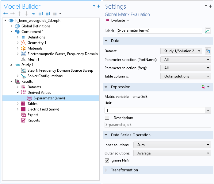
Use the new study step, Frequency Domain Source Sweep, to run a frequency domain study that is sweeping among ports and lumped ports calculating a full S-parameter matrix. The settings for this study step are similar to those for the Frequency Domain study step, and much simpler than the traditional port sweep, which requires a parametric sweep step. You can see this new feature in the H-Bend Waveguide 2D model.
Port Enhancement
The transverse electromagnetic (TEM) port type supporting the user-defined electric potential and ground boundaries is now available in 2D and 2D axisymmetric models. Also, numeric TEM impedance calculation is possible without defining the magnetic field integration line for the current. The port impedance is computed using the average power flow on the port boundary, and the voltage is calculated by the electric field line integration. Lastly, lumped port excitation can now be configured by input power.
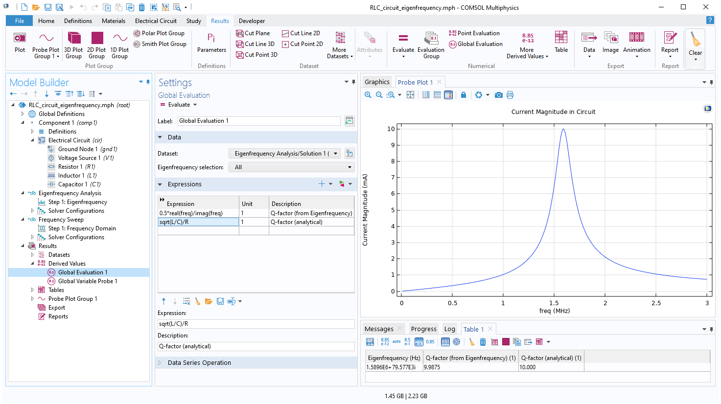
Enhanced Usability of Eigenfrequency Study
The eigenfrequency study has been updated to reduce the number of modeling steps and enhance usability. After the eigenfrequency simulation, the eigenfrequencies and Q-factors are automatically evaluated and presented in a table.
Additional Parts from Signal Microwave
Four new edge-launch connectors are added in the RF part library, provided by Signal Microwave.

Polarization Plot Type
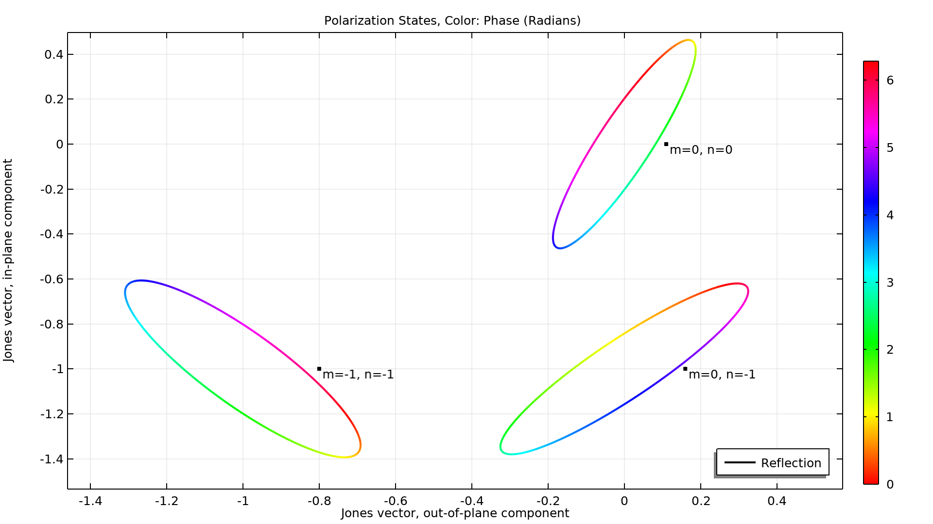
The Polarization plot type depicts the polarization state for the different diffraction orders seen in a periodic structure, such as a frequency-selective surface or metamaterial. It is used for default plots when periodic ports are included in the simulation, and can be added manually when postprocessing. You can see this new plot type used in the Hexagonal Grating (Wave Optics) model.
Oblique Angle of Incidence for Scattering Boundary Condition in Mode Analysis
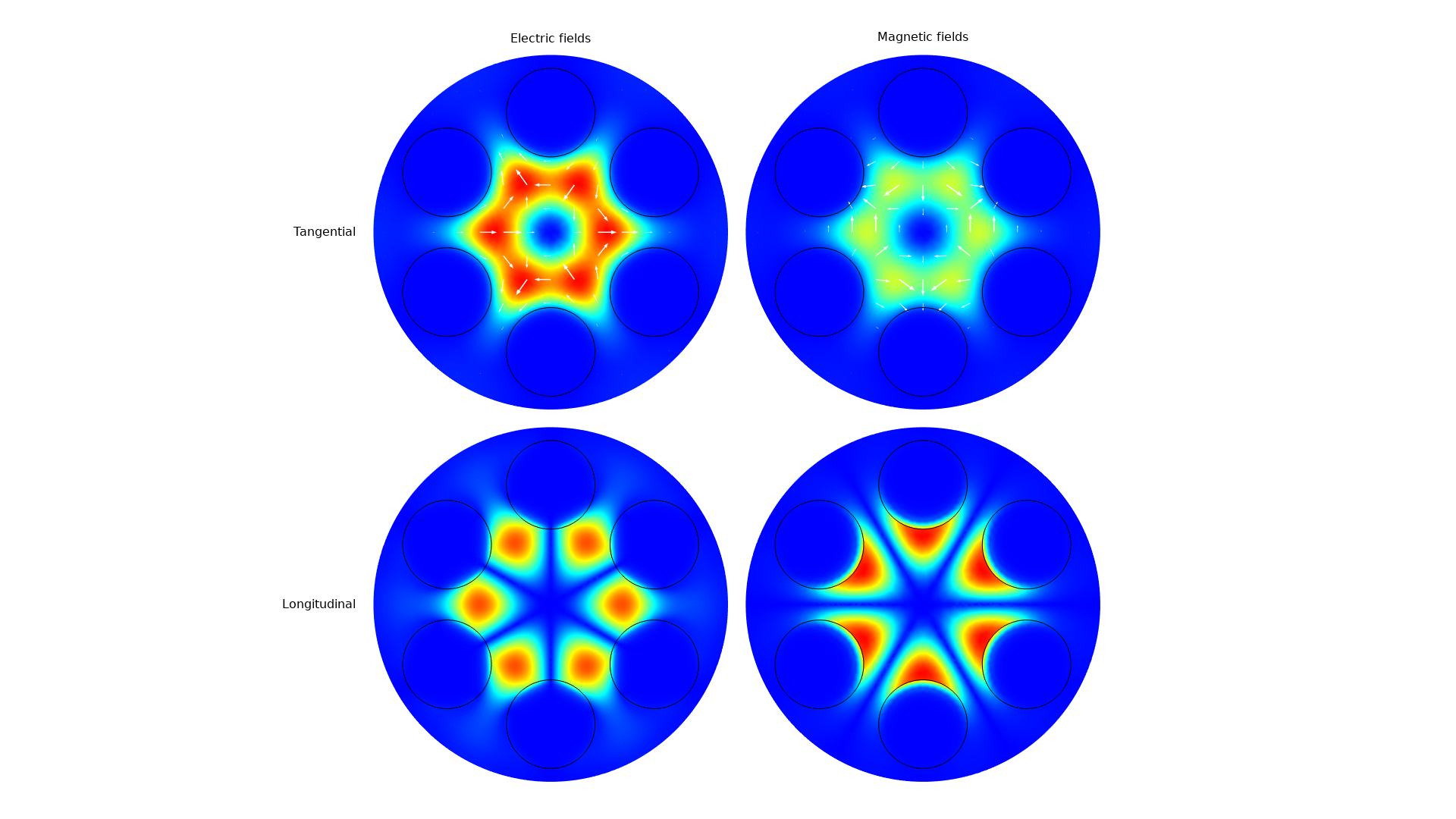
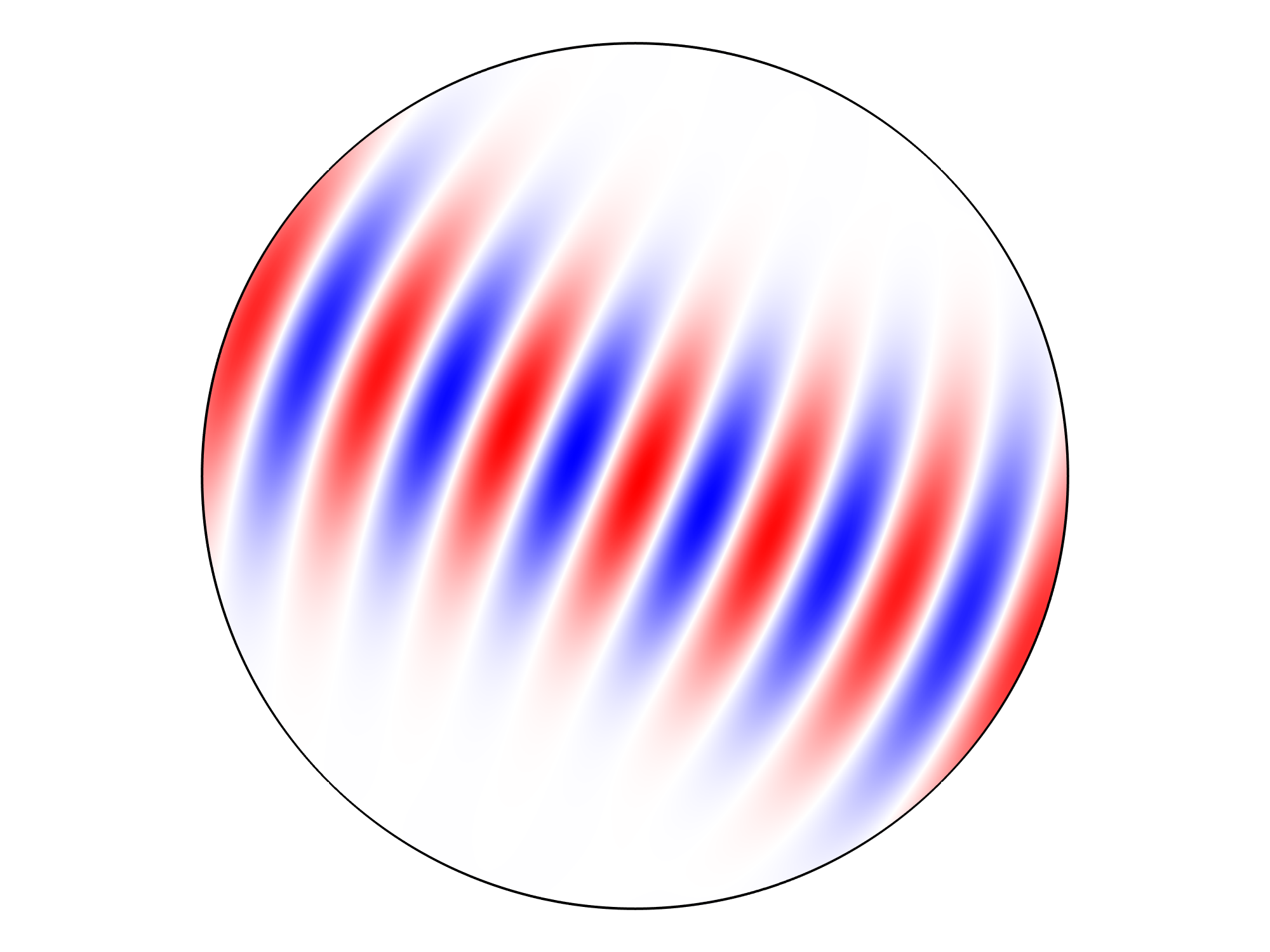
For mode analysis, the Scattering boundary condition can now use an oblique angle of incidence. That is, it can efficiently absorb waves with a wave vector composed of the mode's propagation constant directed tangentially to the boundary and a remaining normal component. This improves loss calculation in mode analyses for lossy waveguides. You can see this new feature in the Leaky Modes in a Microstructured Optical Fiber model.
Input Power to Control Gaussian Beam Amplitude
For Gaussian beam background fields and input fields to the Scattering and Matched boundary conditions, the amplitude of the beam can be specified by providing the input power. You can view this in the Self-Focusing model.
Reference Point Defined by a General Expression
The Reference Point subfeature to the Scattering and Matched boundary conditions can now be specified from a general vector expression. This makes it simpler to parameterize the propagation direction of input Gaussian beams for these boundary conditions.
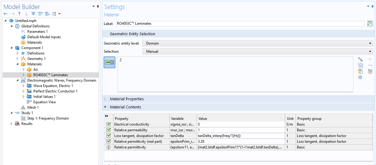
Synchronization of Material Parameters Between Related Material Property Groups
The relative permittivity, refractive index, loss tangent, and dielectric loss material properties can synchronize the material parameters between groups. Thus, if a material is added and specified by the refractive index material property group, the Electric Displacement Field setting in the Wave Equation, Electric node can be any of the mentioned material models. If the required parameters are not directly available in the material, the parameters are created using a synchronization rule.
Wide Support for Eigenfrequency Analysis
The Eigenfrequency study is now supported for most of the AC/DC Module interfaces: Electric Currents, Electric Currents in Shells, Electric Currents in Layered Shells, Electrical Circuit, Electrostatics, and Magnetic Fields. In addition to supporting full-wave cavity mode analysis in the Magnetic Fields interface, it is possible to run eigenfrequency analyses with models involving electrical circuits. The eigenfrequency support is primarily developed for the AC/DC Module, but other modules that provide one of the affected physics interfaces will benefit from it too.
New and Enhanced Functionality for the Electrical Circuit Interface
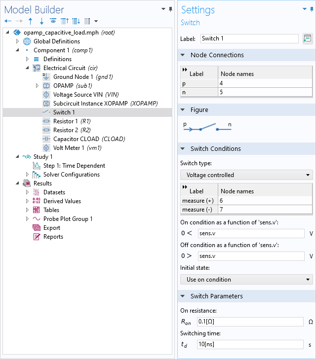
For Time Dependent studies, the Electrical Circuit interface has been equipped with an "event-based" Switch feature. This allows you to model the "instantaneous" on-off switching of certain connections in the circuit. The switch can be current controlled, voltage controlled, or controlled by user-defined Boolean expressions.
Furthermore, Parameterized Subcircuit Definitions are added. Together with the Subcircuit Instance, these allow you to create your own building blocks containing smaller circuits, and use multiple parameterized variants of those in your larger circuit. Finally, the state, event, and solver machinery has been improved, especially the transient modeling of nonlinear (semiconductor) devices, which has become more robust.
The circuit improvements are primarily developed for the AC/DC Module, but other modules that provide access to the Electrical Circuit interface will benefit too. You can view the new functionality in these updated models:
- operational_amplifier_with_capacitive_load
- battery_over_-_discharge_protection_using_shunt_resistances
- p_-_n_diode_circuit
- reverse_recovery_of_a_pin_diode
New Curl Shape Function
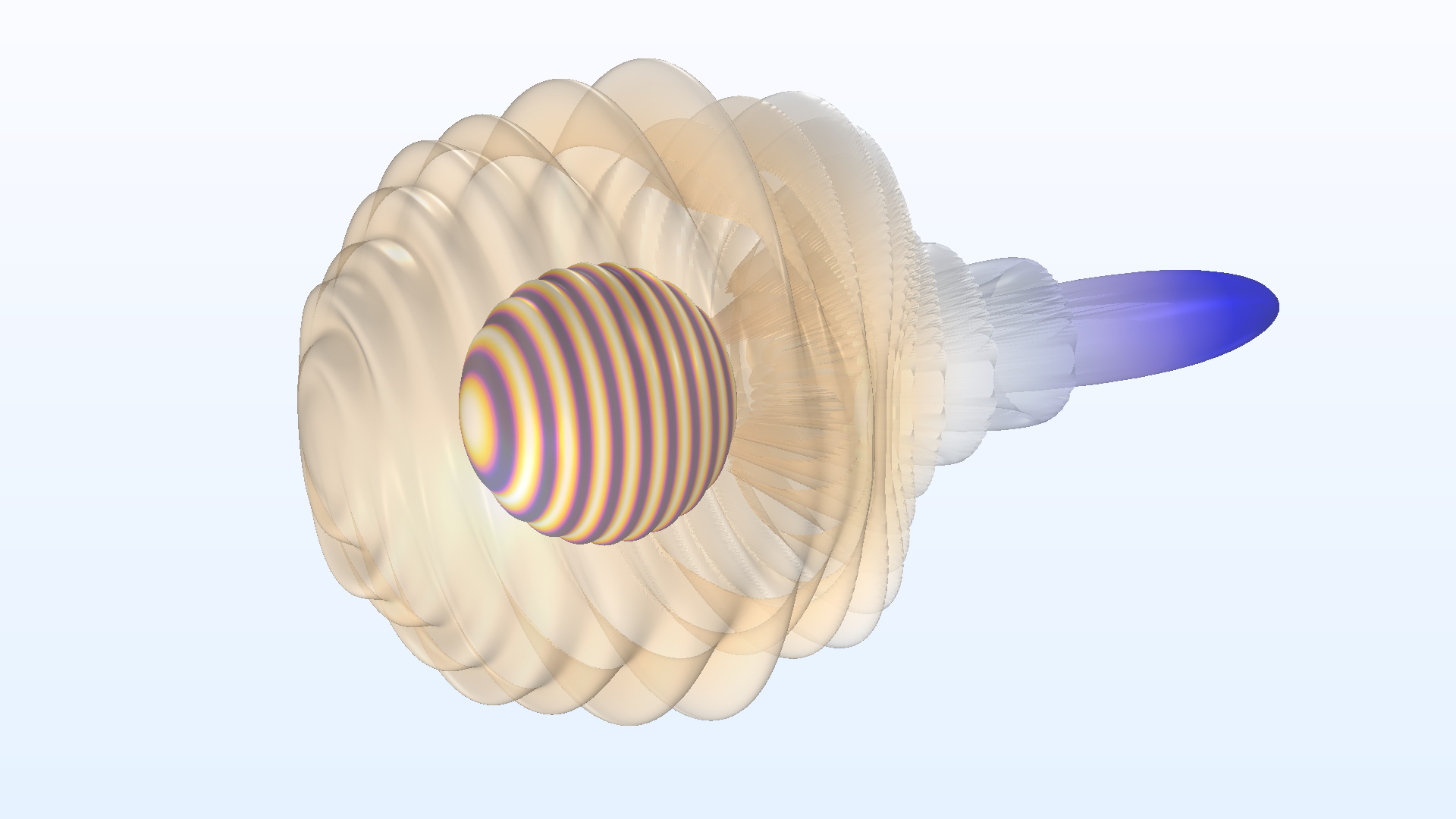
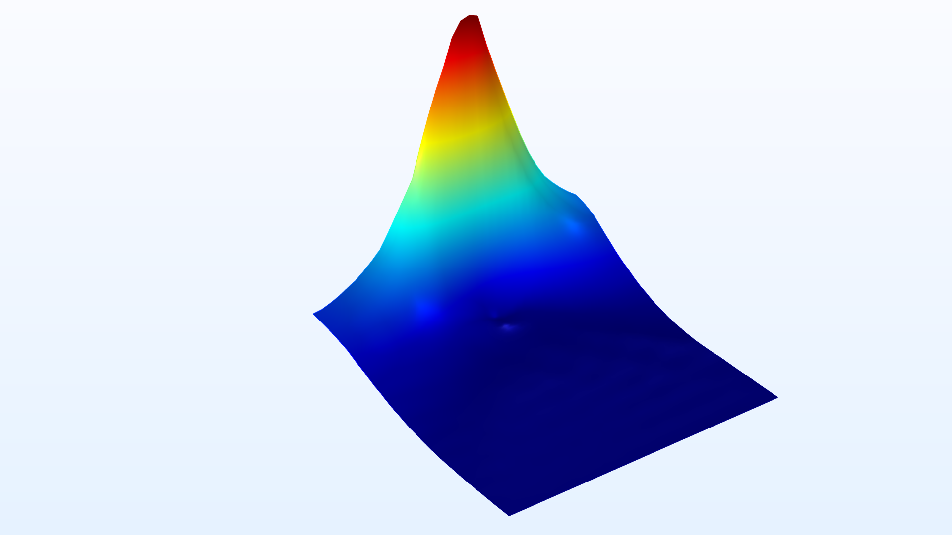
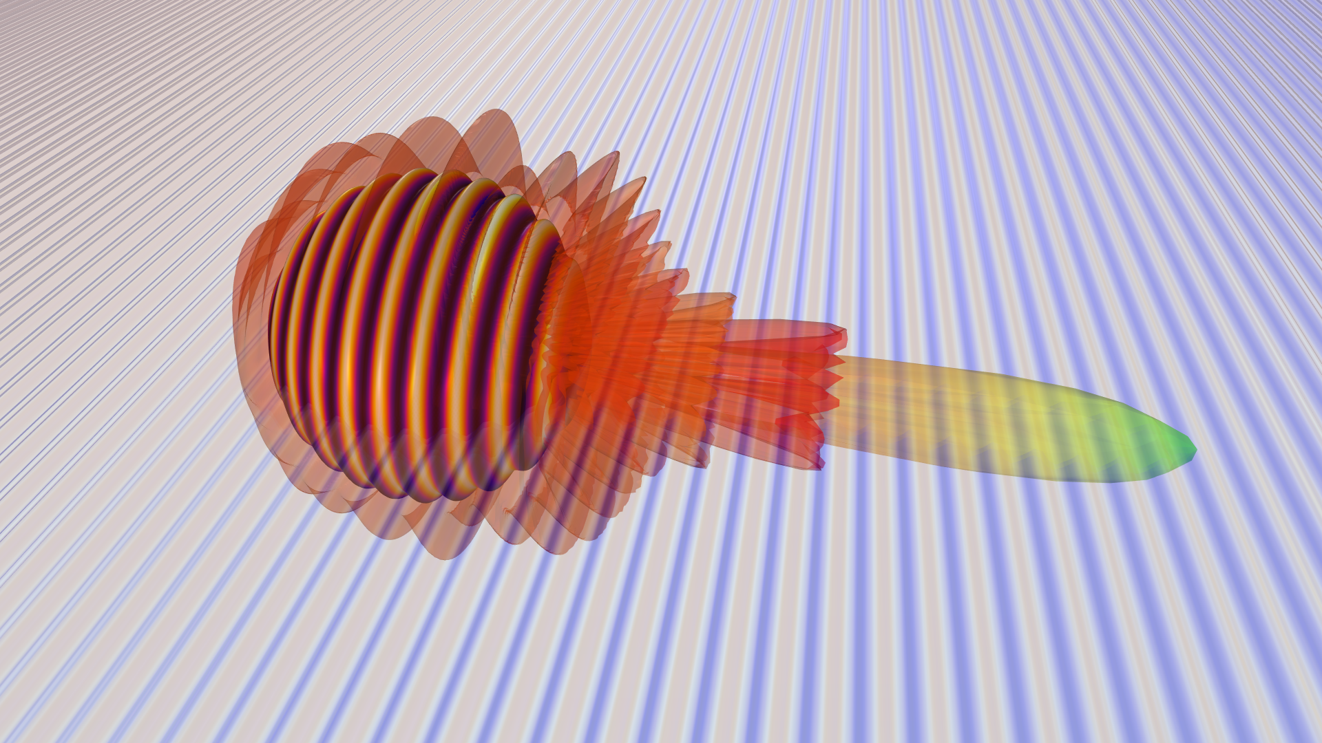
The Nédélec finite element of the second kind is now available. This element type, or shape function, has full polynomial orders in all directions for each field component. This can give a solution to certain finite element problems for lower shape orders, or with coarser meshes, and it can also make the resulting fields look smoother in postprocessing. You can see this new functionality in the Orbital Angular Momentum Beam model.

Updated Tutorial Models Showing Useful Postprocessing Functionality
Several tutorial models in the RF Module Application Libraries have been updated to introduce useful postprocessing features.
| Item | Functionality | Model |
|---|---|---|
| Compute beam width | Half power beam width calculation in a radiation pattern plot | dipole_antenna |
| Transparency subfeature | Partial transparency separately applied on each plot | dipole_antenna cavity_filter_5g |
| Graph Marker subfeature | Maximum and minimum point | cylinder_orientation |
| Touchstone export | Touchstone export using the saved solution | coupled_line_filter |
| Two y-axes | Multiple plots with two y-axes scaled separately | branch_line_coupler |
New Tutorial Models
COMSOL Multiphysics® version 5.6 brings several new tutorial models to the RF Module.
Thermostructural Effect of a Cavity Filter
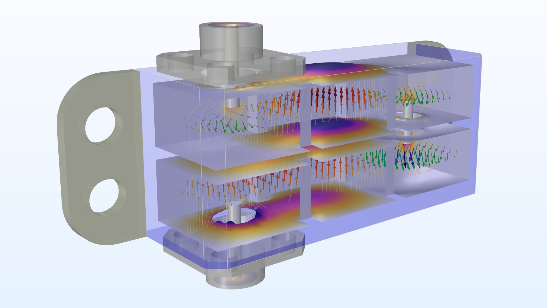
Application Library Title:
cavity_filter_5g
Download from the Application Gallery
Basic Emission and Immunity Analysis of a Circuit Board
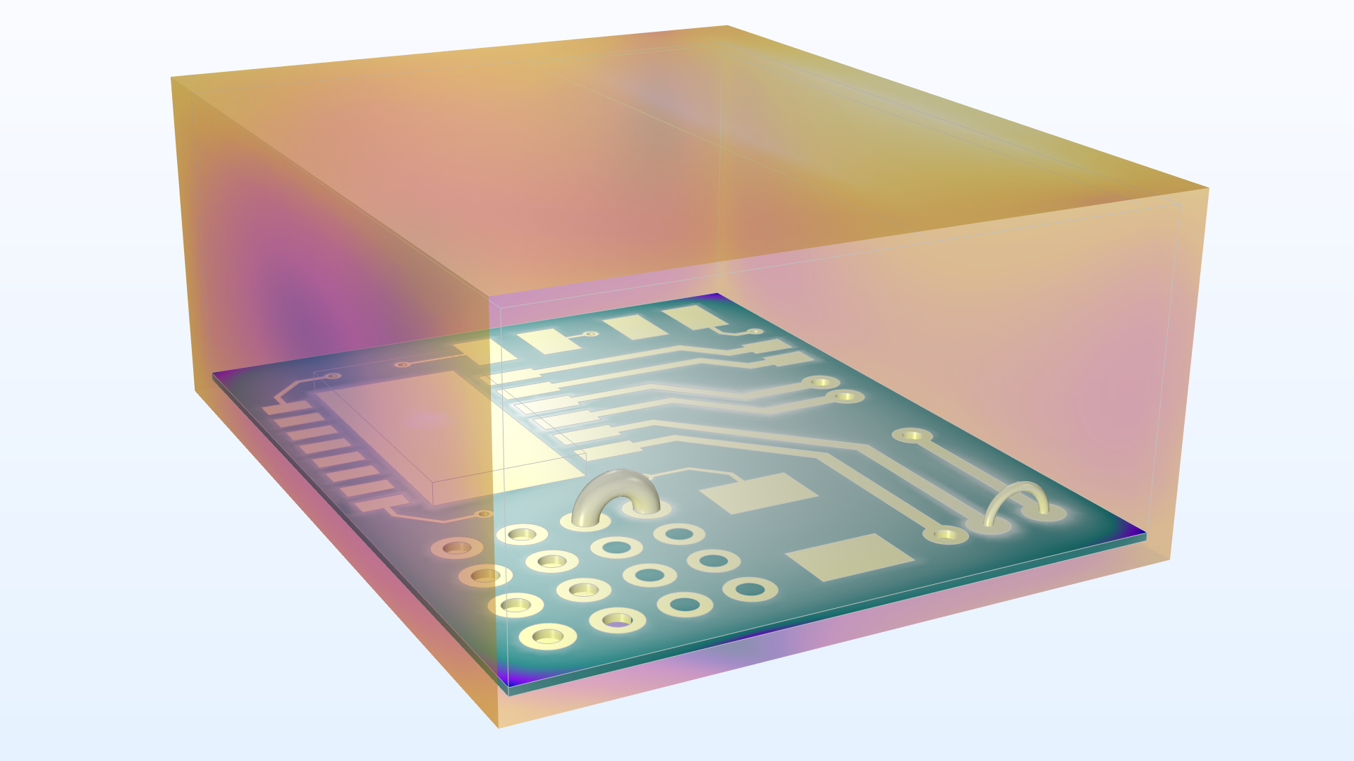
Application Library Title:
circuit_emiemc
Download from the Application Gallery
Fast Asymptotic Radar Cross-Section Analysis of a Conductive Sphere
Application Library Title:
rcs_sphere_asymptotic
Download from the Application Gallery
Modeling of a Phased Array Antenna
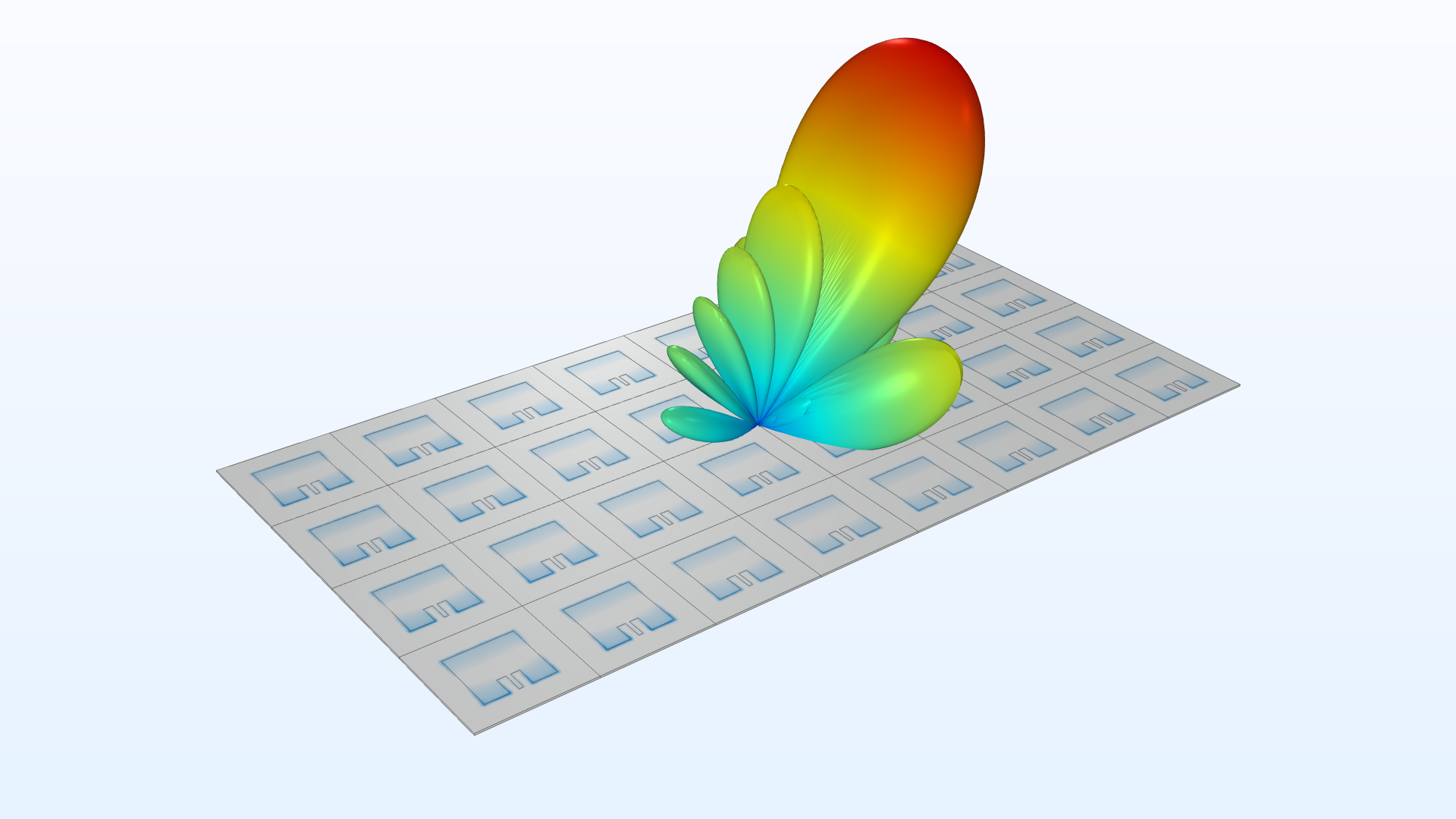
Application Library Title:
microstrip_patch_antenna_periodic
Download from the Application Gallery