Structural Mechanics Module
New App: Viscoelastic Structural Damper
Viscoelastic dampers are frequently used to protect tall structures against vibration. The Viscoelastic Structural Damper application can perform the time-domain and frequency-domain analyses for a typical viscoelastic damper. The purpose of the app is to compute and analyze the important parameters of the damper such as the hysteresis loop and loss and storage moduli for a prescribed material model. In addition, the application provides a visual comparison of the damper behavior when you use two different settings for the viscoelastic material parameters.
You can change the number of viscoelastic branches and their corresponding material parameters as well as the magnitude and phase of the applied load. The app can be used to study the damper over a range of frequencies or as time-dependent problem.
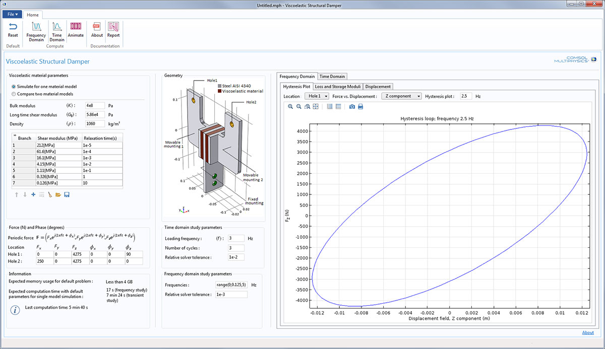 The user interface of the Viscoelastic Structural Damper app, showing the hysteresis plot in the z-direction at Hole 1.
New App: Beam Section Calculator
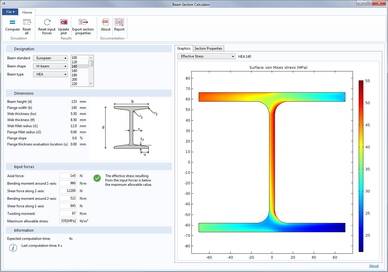
The Beam Section Calculator app allows you to evaluate cross section data for a wide range of American and European standard beams. The computed data can then be transferred for use as input data in the COMSOL Multiphysics® simulation software.
Given a set of forces and moments acting on the section, you can also compute a detailed stress distribution. The app is built upon the Beam Cross Section interface in COMSOL Multiphysics.
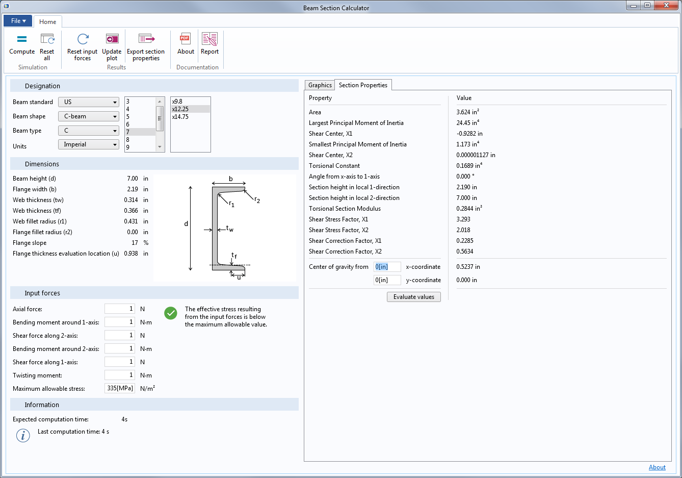 The results for cross section data, computed by the Beam Section Calculator app.
New App: Truss Bridge Designer
The Truss Bridge Designer app is an example of how to design a simulation tool for a class of civil engineering structures, in this case a Pratt truss bridge. Such a bridge is characterized by the diagonal beams on each side of the bridge, which all slant down and in toward the center of the span. Because of this design, the diagonal beams are subjected only to tension, while the vertical beams, which are shorter and thereby less sensitive to buckling, undergo compression.
In the app, you can change all of the major geometrical dimensions of the roadway and the supporting beams. You can also provide loading in terms of any number of trucks and a sideways-acting wind load. In addition to the stationary study, which computes the displacements and stressed caused by the loads, you can compute the natural frequencies of the bridge.
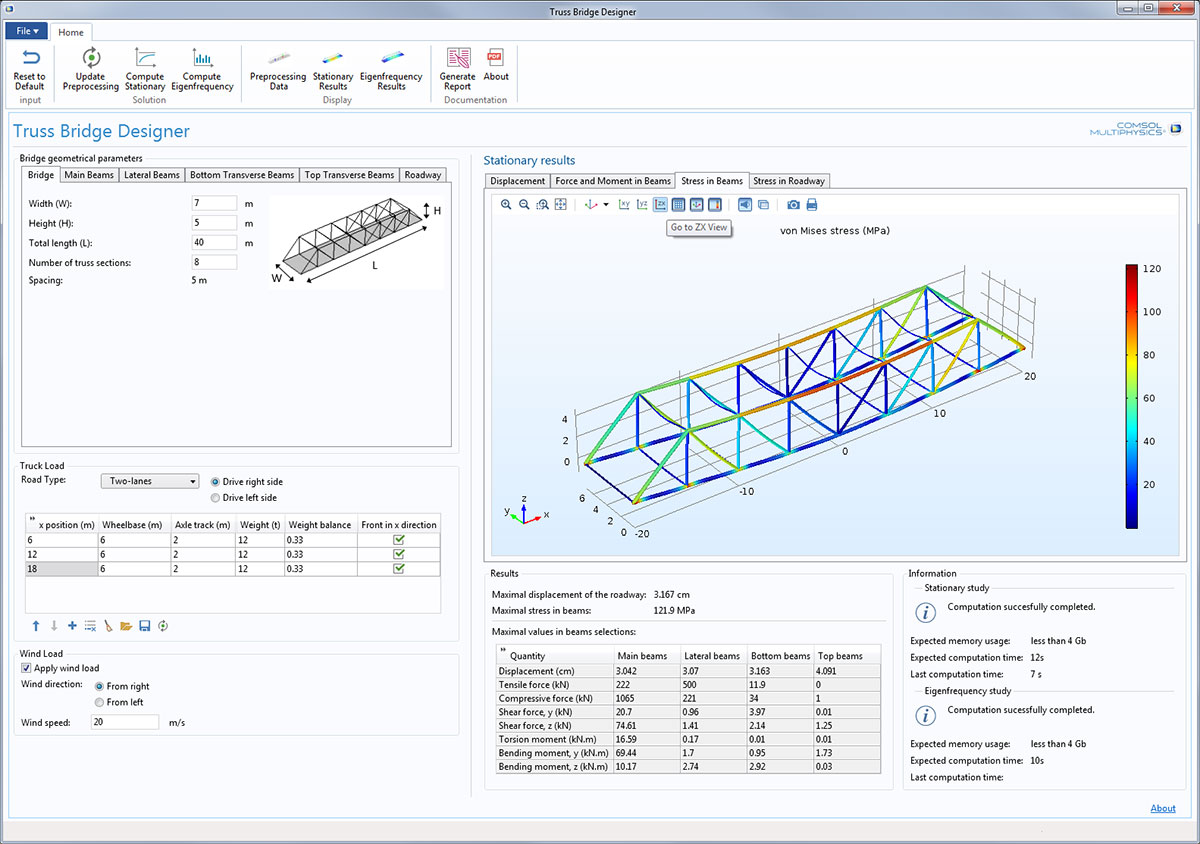 In the Truss Bridge Designer app, stresses in the supporting beams are shown in one of the results tabs.
New App: Linear Buckling of a Truss Tower
Buckling analysis is the search for the critical compressive load beyond which structures become unstable. The Truss Tower Buckling analysis application simulates the buckling of a truss tower under vertical compressive loads to provide the critical compressive load.
With the app, you can compute and analyze the buckling load for a tower under different conditions of geometry, i.e., various tower heights, cross-sectional area, as well as different materials. You can choose whether the tower will be unstayed or supported by guy wires. The app takes into account the effect of dead load (self-weight of truss and supporting guy wires and their pre-tension) while performing the computation.
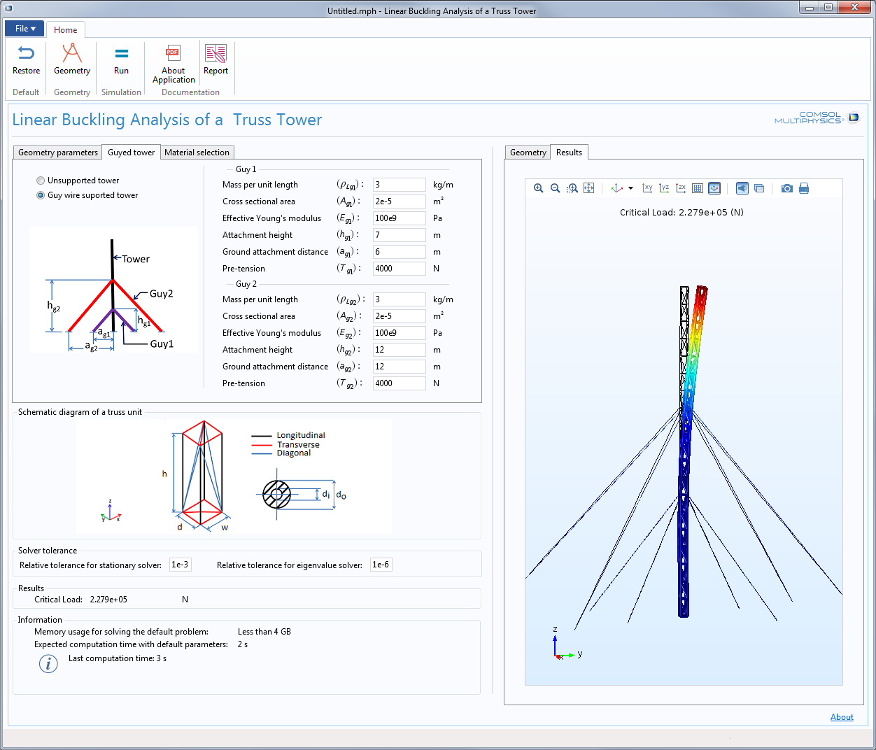 The Linear Buckling of a Truss Tower app computes the buckling mode for a guyed tower.
New App: MEMS Pressure Sensor Drift Due to Hygroscopic Swelling
For their integration in microelectronic circuits, MEMS devices are bonded on printed circuit boards and connected with other devices. Then, the whole circuit is often covered with an epoxy mold compound (EMC) to protect the devices and their interconnects with the board. The epoxy polymers used for such applications are subject to moisture absorption and hygroscopic swelling, which can lead to delamination between the EMC and the board or to incorrect behavior of MEMS components.
The MEMS Pressure Sensor Drift app simulates the drift of the measured strain over time due to hygroscopic swelling on a MEMS pressure sensor subject to a moist environment. The app helps the designer to reach the required sensitivity and minimize the drift. This is done by specifying geometrical parameters, mold compound material properties, and external conditions.
The app was built utilizing the Transport of Diluted Species, Solid Mechanics, and Shell interfaces in the COMSOL Multiphysics® software.
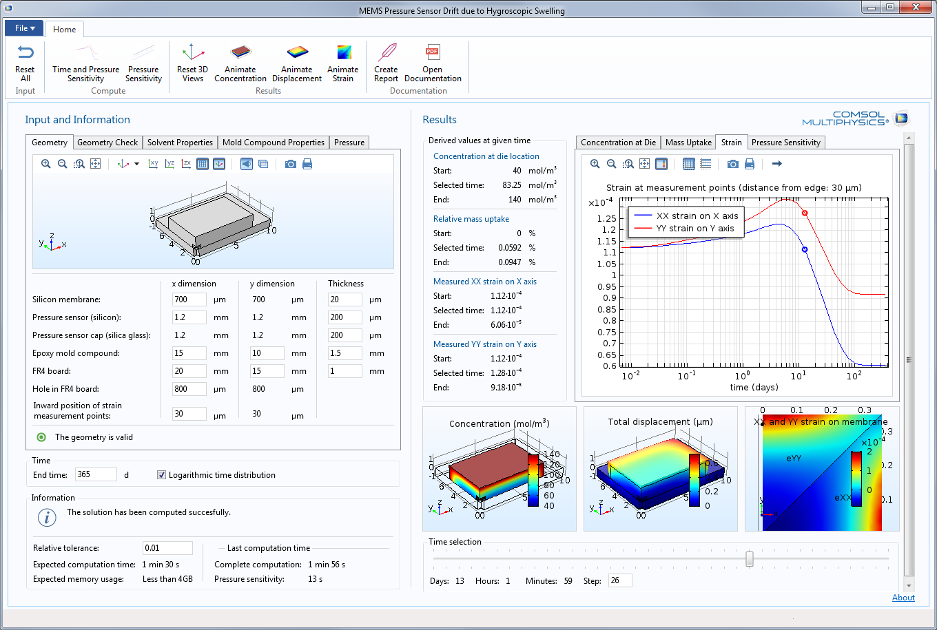 The MEMS Pressure Sensor Drift Due to Hygroscopic Swelling app, showing results from a simulation of pressure sensor stability.
New App: Interference Fit
The purpose of the Interference Fit Calculator application is to study the connection in an interference fit where one pipe is shrunk over another pipe. Since the inner pipe is larger than the available space given by the outer pipe, the inner pipe is compressed while the outer pipe expands.
The resulting contact pressure will thus depend on the initial geometry of both parts. Furthermore, the transferable torque and force depend on the friction force between the two parts, which is proportional to the contact pressure.
In the app, you can modify the pipe geometries, the size of the overlap region, and the friction coefficient. Upon doing so, the app displays the effective stress in the assembly, the contact pressure at the interface between the two pipes, and the deformation of the two pipes at the interference diameter.
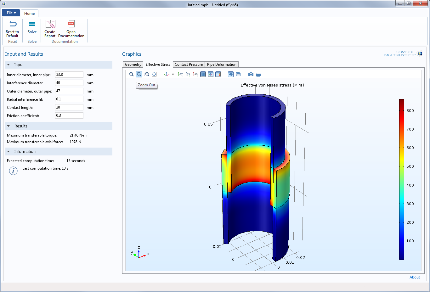 Results for the computed stresses in the Interference Fit app.
Material Models from Externally Programmed Libraries
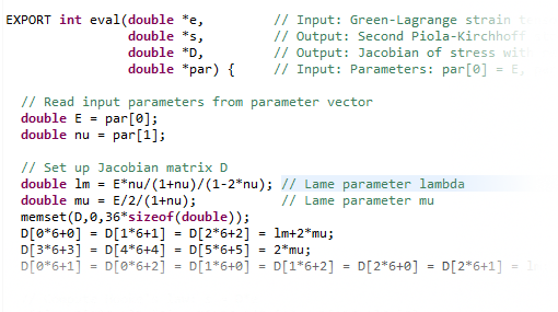
A new way to specify user-defined material models is included in COMSOL Multiphysics version 5.2. You can now access external material functions, written in C code, which have been compiled into a shared library. By writing a wrapper function in C code, you can also use material functions written in another programming language. This makes it possible to program your own material models and distribute such models as add-ons.
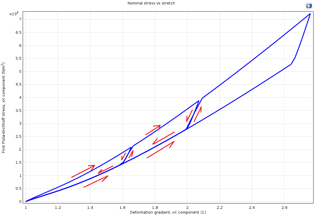
The external library can either completely define the stress-strain relation, or only return an inelastic strain contribution to the available material models. Using only an inelastic strain contribution is quite powerful in itself. It allows for the implementation of materials similar to the built-in material models available as subnodes under the Linear Elastic Material node; for example, plasticity and creep. The complete stress-strain relation, on the other hand, corresponds with a top-level material node, such as the Cam-Clay material model, and is used to define a material model from the ground up.
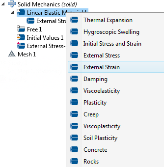
Two new features are available in the Solid Mechanics interface to accommodate this new functionality: the External Stress-Strain Relation material model and the External Strain subnode under the Linear Elastic Material node.
The existing user-defined options in the Hyperelastic Material, Plasticity, and Creep nodes, for example, provide a convenient, but more limited way of defining your own material models.
Add an External Stress-Strain Relation as the material for some domains.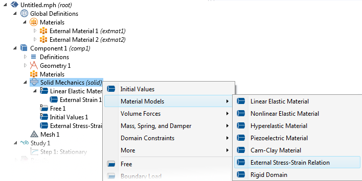
Add an External Stress-Strain Relation as the material for some domains.
Contact with Small Relative Displacements
COMSOL Multiphysics version 5.2 introduces a new, simplified method for computing the distances within contact pairs. You can use this functionality when there is little sliding between the contacting surfaces, such as in a shrink fit or when two parts are bolted together. In this method, the mapping between the source and destination is computed only once, which leads to faster and more stable convergence. To use this method, set the mapping method to Initial configuration in the settings window for the contact pair.
Initial Contact Gap Adjustment
Sometimes, the finite element discretization of curved boundaries causes the initial distance between the two boundaries in a contact pair to have noticeable irregularities. You can now compensate for this issue through a built-in computation of the initial gap. This initial gap can then be subtracted in the subsequent analysis if you select the Force zero initial gap check box in the Contact settings window in the Solid Mechanics interface.
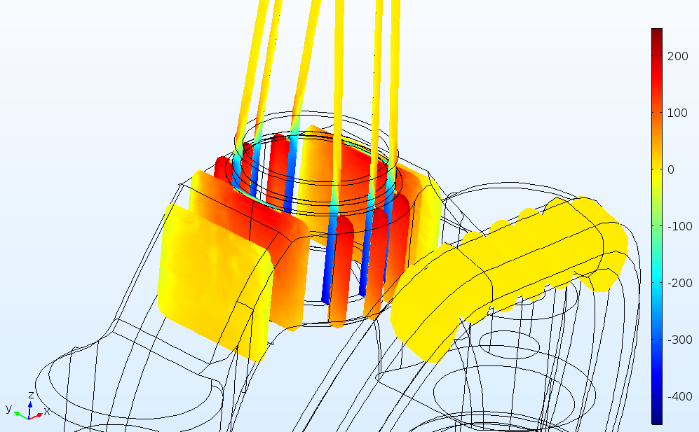
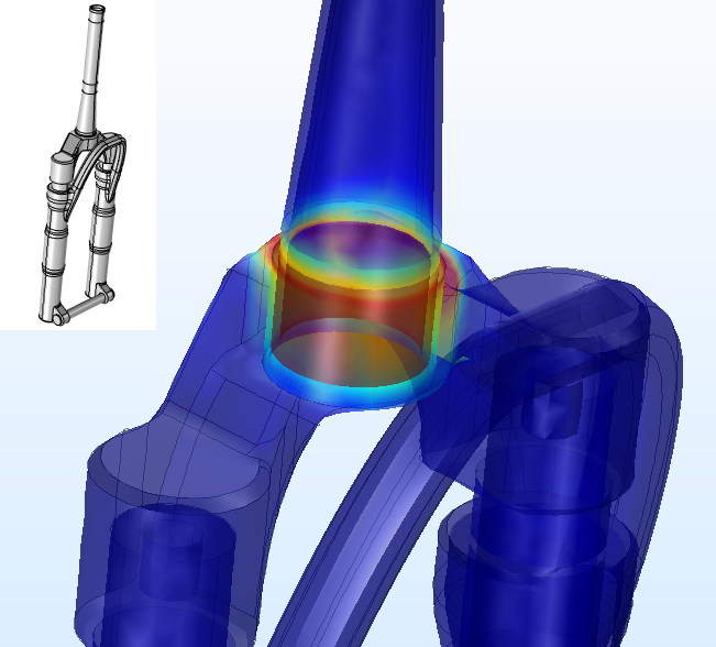 Stresses caused by the shrink fit between the steering tube and crown in a bike fork (from the new Interference Fit Connection in a Mountain Bike Fork tutorial).
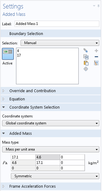
Full Mass Matrix Input in Added Mass
The Added Mass feature has been extended so that it is possible to enter a full mass matrix.
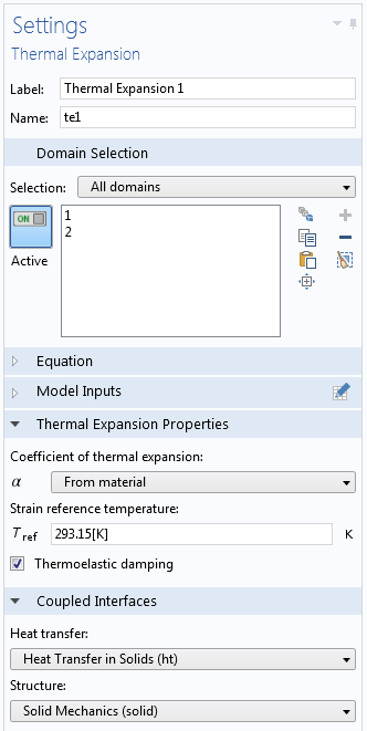
Optional Inclusion of Thermoelastic Damping
In the Thermal Expansion multiphysics coupling, you can now select whether or not the time derivative of the stresses should act as a heat source in the heat transfer problem. By selecting the new Thermoelastic damping check box, the problem will become two-way coupled when a time-dependent problem is solved.
Prescribed Velocity/Acceleration Interpretation in Stationary Analysis
When the Prescribed Velocity or Prescribed Acceleration nodes are present in your model, you can define how these boundary conditions should be interpreted in a stationary analysis. They can either be treated as a constraint (constrained), or ignored (free). This is particularly useful in models and apps with multiple mixed-analysis types, including frequency-domain, time-dependent, and stationary types.
New Model: Interference Fit Connection in a Mountain Bike Fork
Interference fit is a technique used to join or fit one part over or around another part. The internal part is cooled, so that it shrinks, and is then fitted. Once the part heats up again and expands, a contact pressure builds up at the interface between the two parts.
This type of connection is simulated in a tutorial example of a mountain bike fork where the steering pipe is connected to the crown. The simulation investigates the contact pressure and stress distribution as well as the transferable force and torque.
 Maximum and minimum principal stresses at the connection between the steering tube and crown.