Wave Optics Module
New App: Simulation of Concentric Optical Fibers
The transmission speed of optical waveguides is superior to microwave waveguides because optical devices have a much higher operating frequency than microwaves, enabling a far higher bandwidth. Single-mode step-index fibers are used for long-haul (even transoceanic) communication, whereas both graded-index and step-index multimode fibers are used for short-distance communication, for example, within institutions and university campuses and buildings.
For almost all commercial optical fiber types, the design consists of a concentric layer structure with the inner layer(s) forming the core and the outer layer(s) forming the cladding. Since the core has a higher refractive index than the cladding, guided modes can propagate along the fiber.
The Optical Fiber Simulator app performs mode analyses on concentric circular dielectric layer structures. Each layer is described by an outer diameter and the real and imaginary parts of the refractive index. The app can by used for analyzing both step-index fibers and graded-index fibers. These fibers may have an arbitrary number of concentric circular layers.
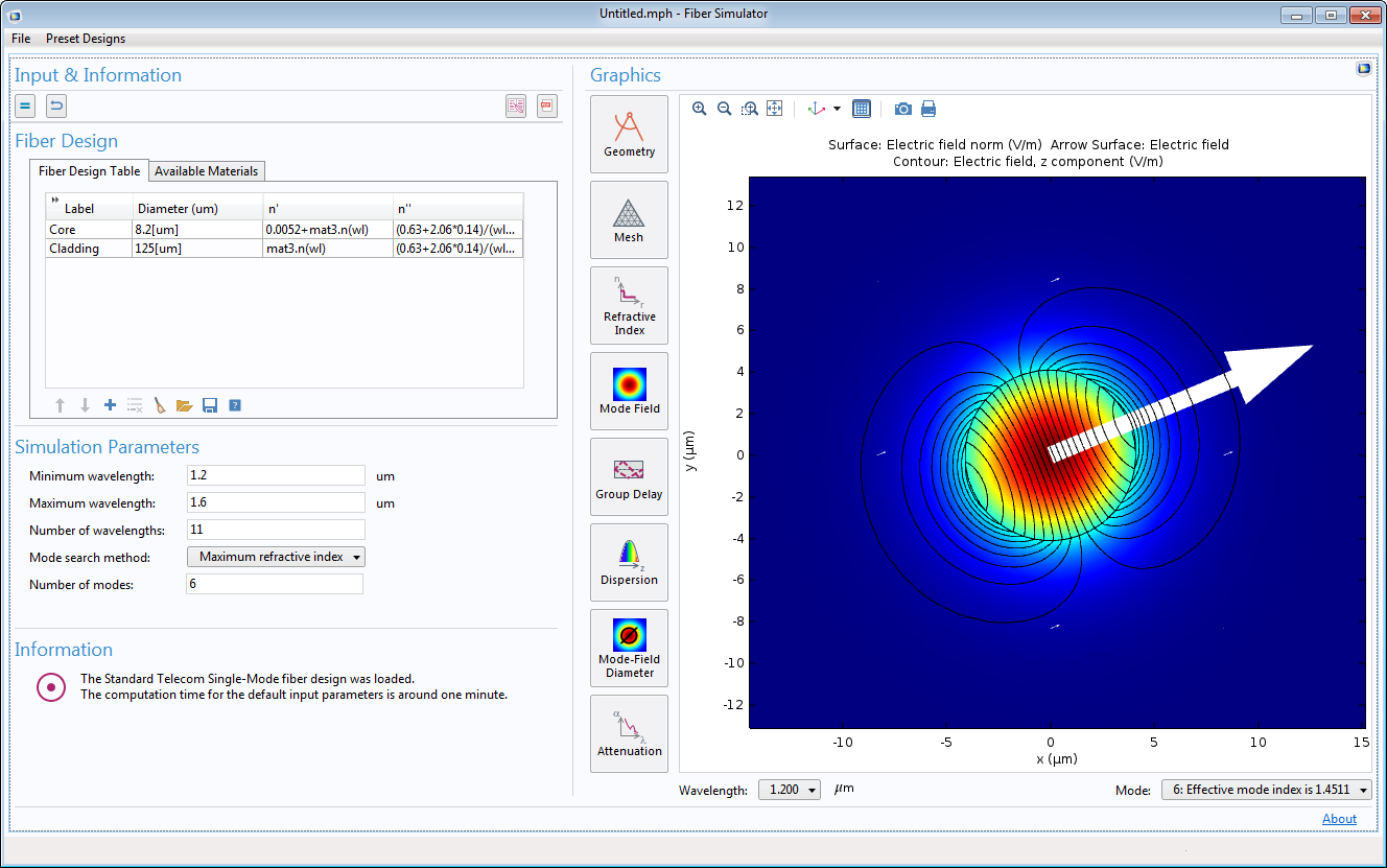 The Simulation of Concentric Optical Fibers app user interface, showing the Mode Field plot.
Enhanced Physics-Controlled Mesh for Handling Lossy Media
The physics-controlled mesh takes lossy electric and magnetic media and automatically scales the size by skin depth on the lossy domain boundaries. When Resolve wave in lossy media is selected, the outer boundaries of lossy media domains are meshed in free space with a maximum mesh element size, given by the minimum value of half of a skin depth and 1/5 of the vacuum wavelength.
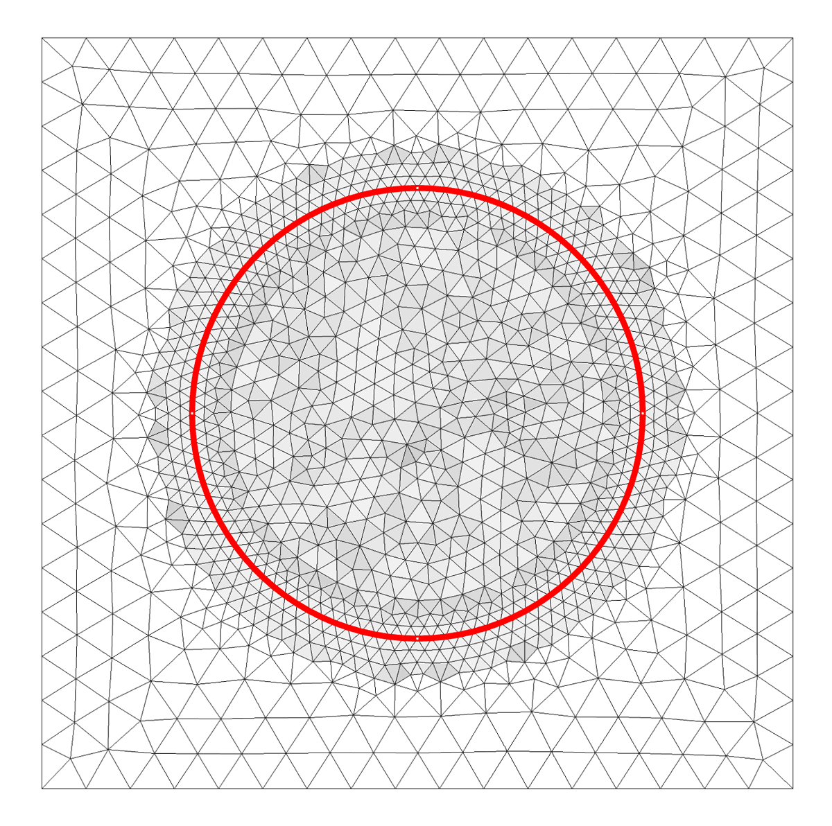 Finer mesh along the outer boundary of a circular lossy media in the air is characterized by the skin depth with these material properties: loss tangent and dissipation factor (ε' = 1.2 and tanδ = 3.5) at 1 GHz.
"Boundary Mode, Frequency-Stationary" and "Boundary Mode, Frequency-Transient" Study Sequences
There are new study sequences in the Model Wizard for the Laser Heating and Microwave Heating multiphysics interfaces in the Wave Optics and RF Modules, respectively. The Boundary Mode, Frequency-Stationary study sequence adds a Boundary Mode Analysis study step and a Frequency-Stationary study step. The Boundary Mode, Frequency-Transient study sequence adds a Boundary Mode Analysis study step and a Frequency-Transient study step. The Boundary Mode Analysis study step is used for solving the mode field for numeric ports in the electromagnetic interfaces. The Frequency-Stationary and Frequency-Transient study steps couple stationary and transient analyses for the Heat Transfer in Solids interface, with a frequency domain analysis for the Wave Optics and RF interfaces.
The Model Wizard panel displaying the availability of the new Boundary Mode, Frequency-Stationary and Boundary Mode, Frequency-Transient study sequences, in this case used with the Laser Heating multiphysics interface in the Wave Optics Module.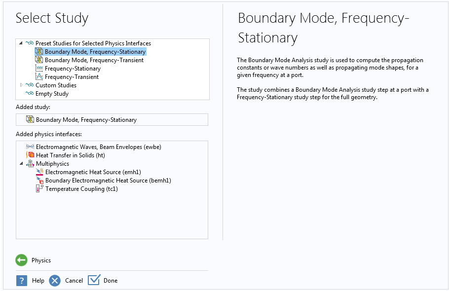
The Model Wizard panel displaying the availability of the new Boundary Mode, Frequency-Stationary and Boundary Mode, Frequency-Transient study sequences, in this case used with the Laser Heating multiphysics interface in the Wave Optics Module.
Initial Value Settings for the Transient Scattering Boundary Condition
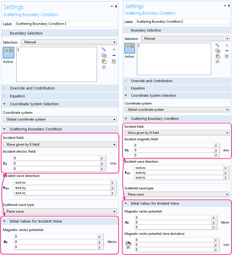
In the settings for the Scattering boundary condition for time-dependent simulations, there is a new section called Initial Values for Incident Wave for setting the initial values of the magnetic vector potential for the incident wave. Note that the section is initially collapsed by default. When the incident wave is defined by an electric field, the user can specify the initial value for the magnetic vector potential for the incident wave. When the incident wave is defined by a magnetic field, the user can specify the initial value for the time derivative of the magnetic potential, in addition to the initial value for the magnetic vector potential. The new settings enable the user to define the exact wave form for the magnetic vector potential being solved for.
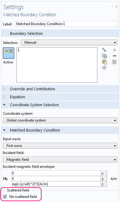
"No Scattered Field" Setting for the Matched Boundary Condition
To prevent spurious solutions from appearing when using the Matched boundary condition with the Electromagnetic Waves, Beam Envelopes interface, a new setting has been introduced – the No scattered field check box. When this check box is marked, the scattered wave is constrained to be zero on the boundary for which the feature is selected. An example that uses this new setting is the Gaussian Beam Incident at the Brewster Angle tutorial model.