Metal Processing Module

Simulate Metallurgical Phase Transformations in Mechanical Components

When a material like steel or cast iron undergoes heating or cooling from an elevated temperature, metallurgical phase transformations may occur. The Metal Processing Module is an add-on product to the COMSOL Multiphysics® simulation software that helps you study how these phase transformations affect the mechanical and thermal properties of the materials. The module includes functionality for modeling phase transformations that are deliberate (such as in steel quenching and carburization) and introduced inadvertently (in additive manufacturing and welding, for example), as well as functionality for annealing. The built-in multiphysics capabilities help you improve the performance of a component by optimizing the phase composition.

Contact COMSOL
A gray metal spur gear model with a small slice shown in red, white, and blue.

Steel Quenching

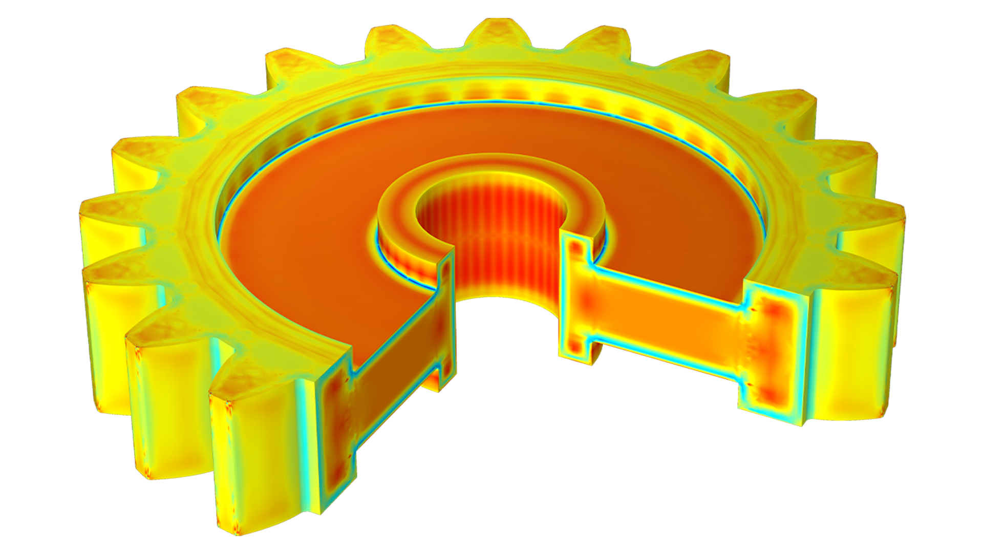
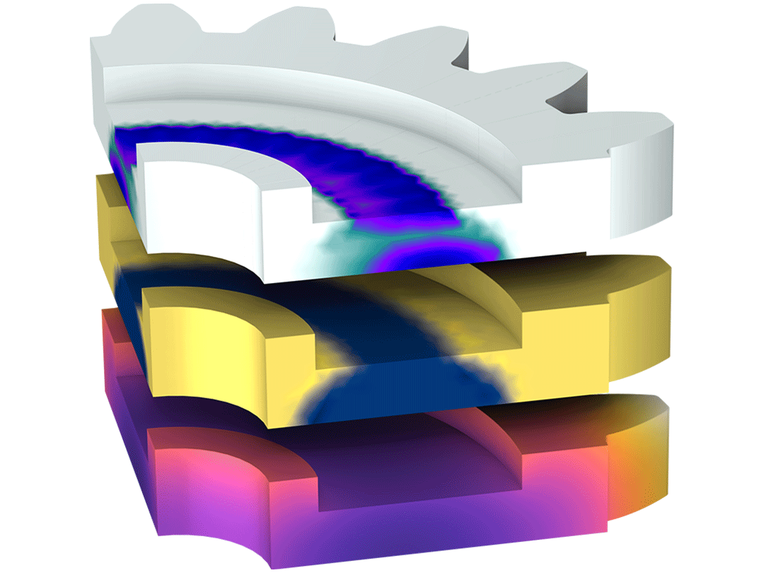
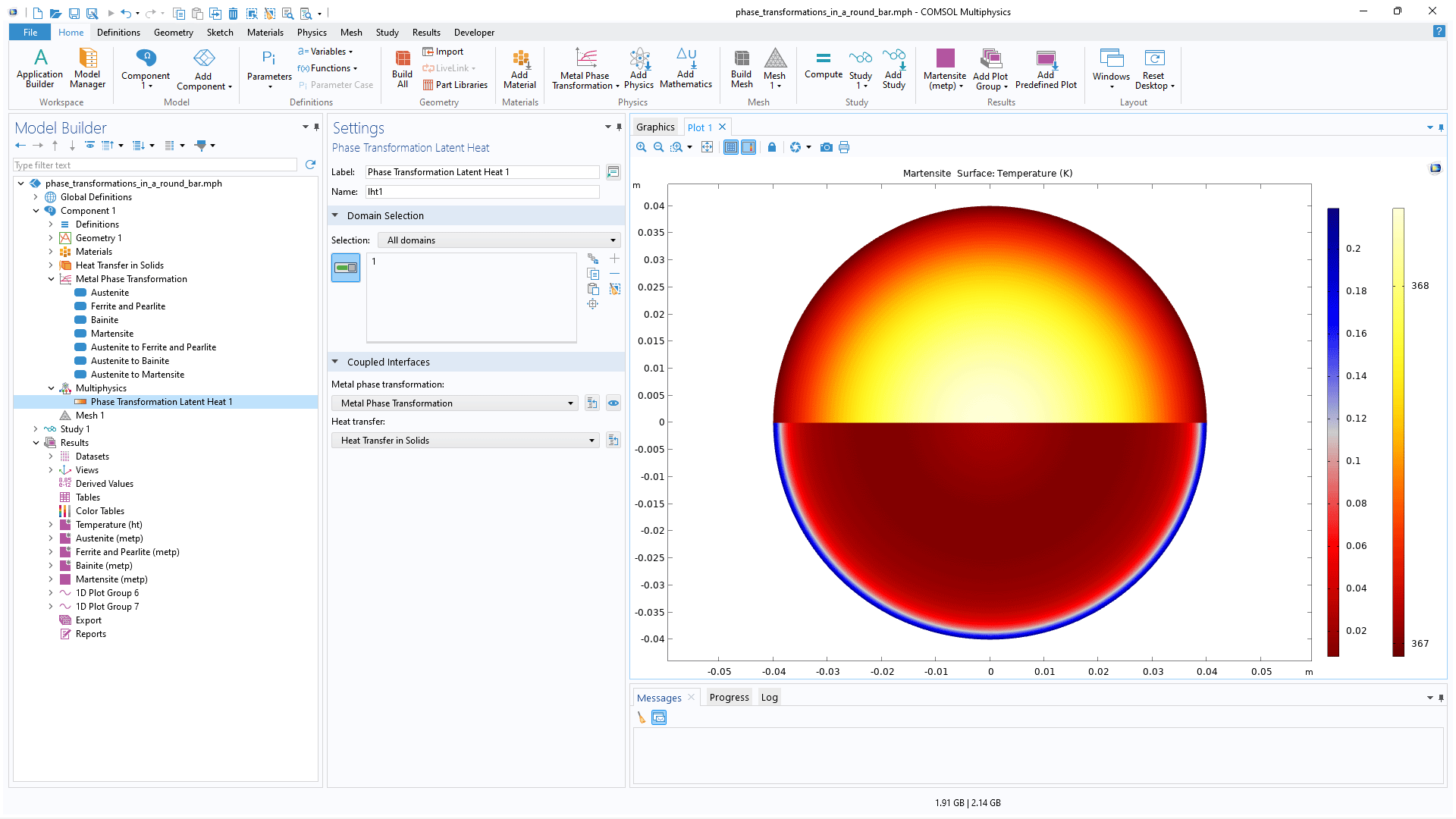
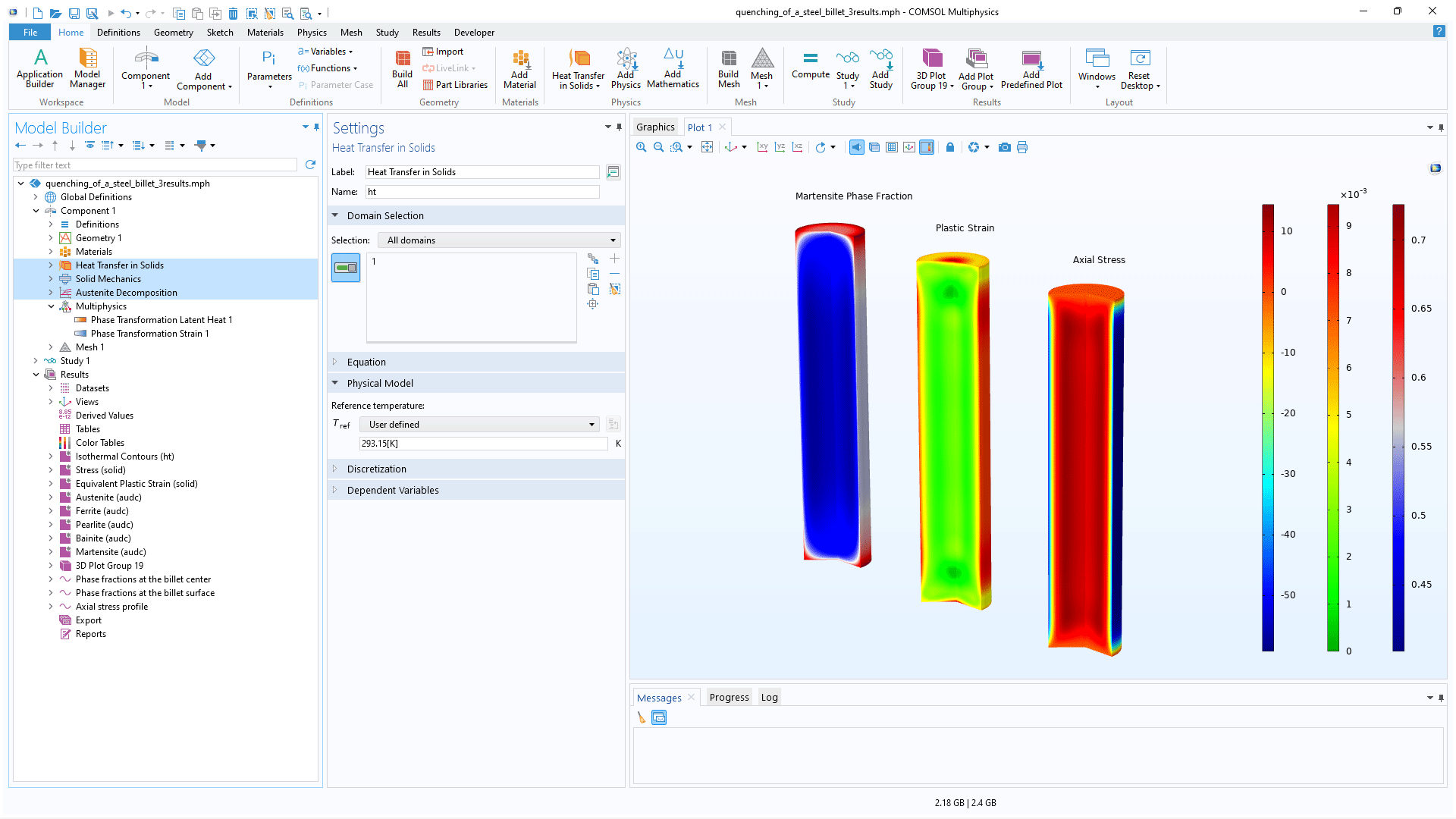
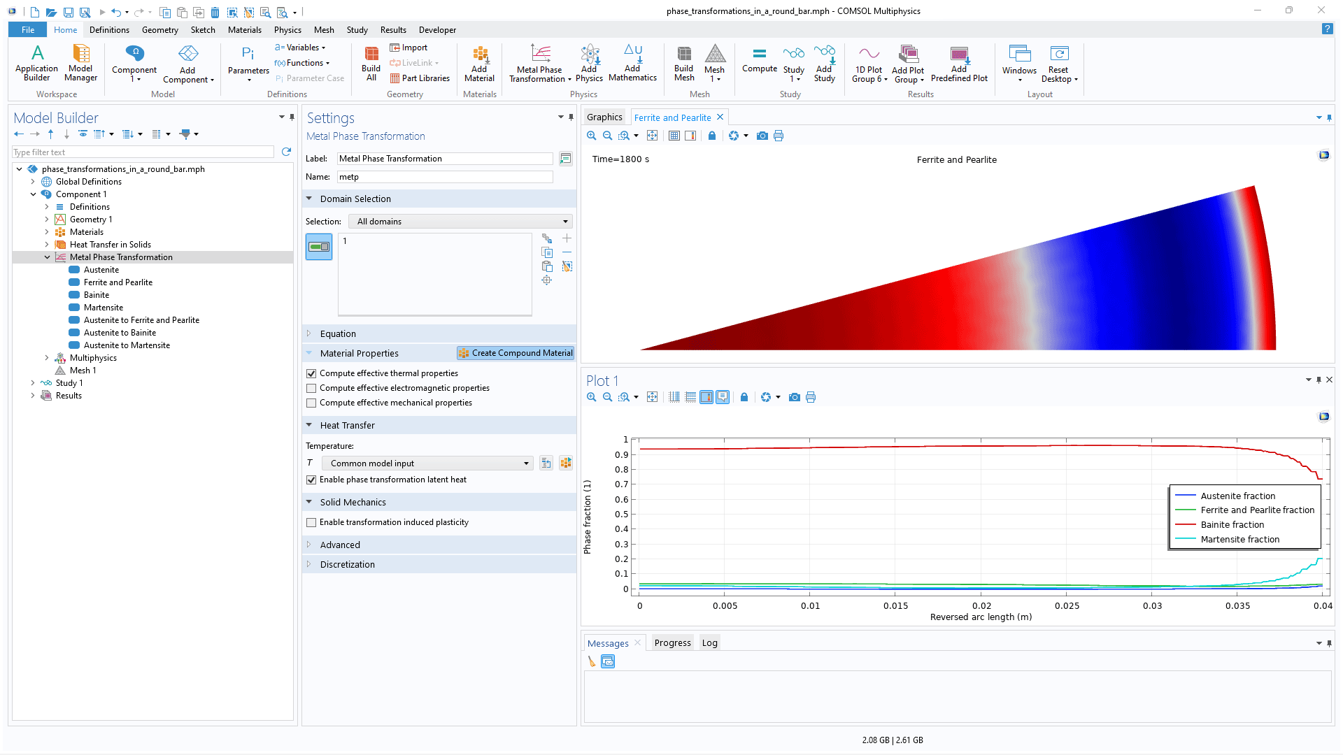
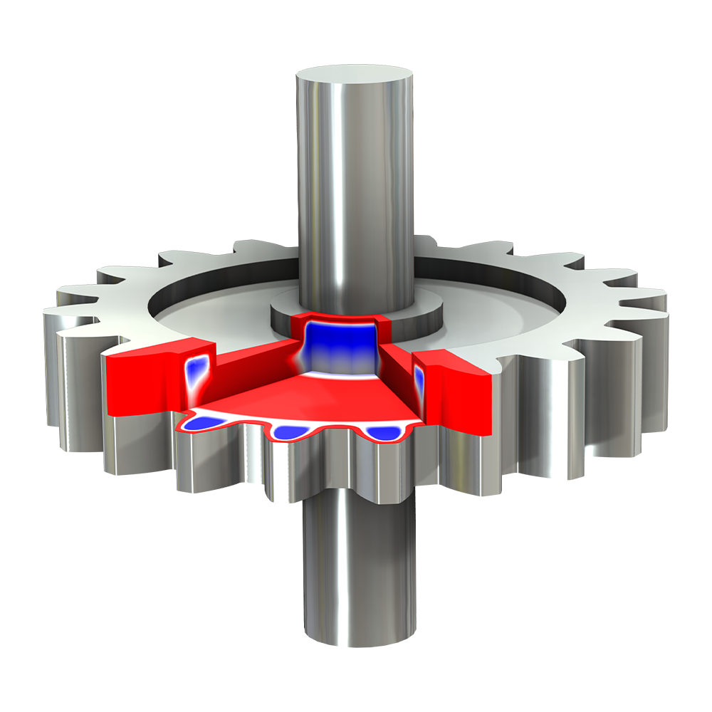
Steel quenching is a heat treatment process where steel parts that have been heated to a fully austenitic state are rapidly cooled. Steel quenching is also a multiphysics process, as it involves a combination of austenite decomposition, heat transfer, and structural analysis. The Metal Processing Module provides specialized features and functionality to facilitate the model setup for this multiphysics process.

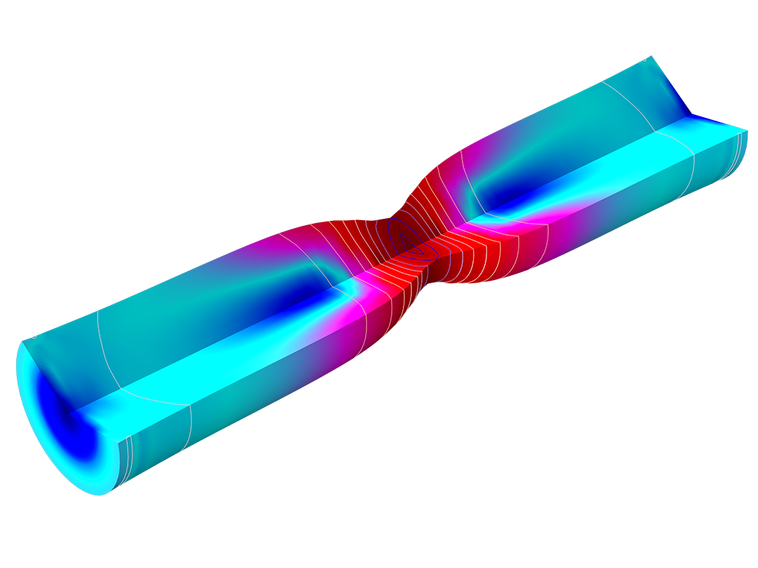
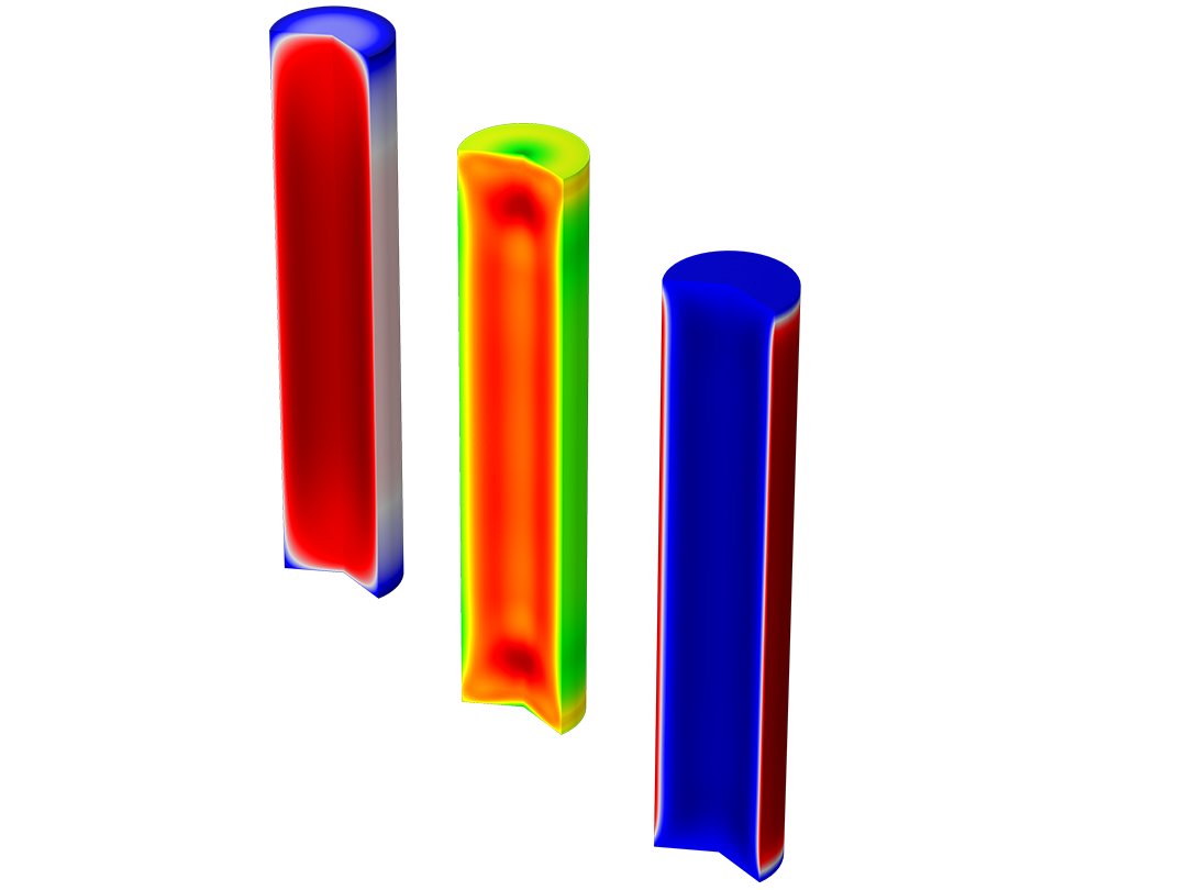
After running the analysis, you can examine phase compositions and the influence of cooling rate on the final distortions and residual stresses during the quenching of a component. These results provide insight into the efficacy of a certain quenchant and how the physical geometry of a component affects the attainable phase composition in its interior.

Carburization

The process of carburization involves heating a steel component and exposing it to a carbon-rich environment, such as carbon monoxide. Diffusion of carbon from the surrounding environment occurs through the boundary and into the material by means of a time-dependent diffusion process. Running carburization analyses helps ensure that the process is carried out correctly. Carburization followed by quenching can produce compressive stresses at the surface of a component, which helps reduce the risk of fatigue.

Annealing

Modeling the heating of steel that has undergone plastic deformation is often necessary. When exposed to sufficiently high temperatures, steel loses its previous work hardening, and this effect should be included in the computational model. The Metal Processing Module, combined with the Nonlinear Structural Materials Module, provides annealing modeling capabilities. These allow for the specification of an annealing temperature; at or above this temperature, the prior work hardening of the steel is eliminated by a reset of the plastic hardening variables.

This modeling capability is particularly valuable in scenarios involving thermal cycling, such as multipass welding. In these situations, the residual stress state of the material is significantly influenced by its plastic history.

Features and Functionality in the Metal Processing Module

Model metallurgical phase transformations and related phenomena.

A closeup view of the Phase Transformation settings and a 2D plot of the austenite phase fraction.

Metal Phase Transformations

The Metal Phase Transformation interface is used for studying metallurgical phase transformations that occur in a material like steel during heating or cooling. With the Metallurgical phase feature you can define the initial phase fraction and material properties; with the Phase transformation feature you can define the source phase, destination phase, and phase transformation model.

For diffusion-controlled phase transformations, such as when austenite decomposes into ferrite, three types of phase transformation models are provided: Leblond–Devaux, Johnson–Mehl–Avrami–Kolmogorov (JMAK), and Kirkaldy–Venugopalan. For modeling displacive (diffusionless) martensitic phase transformations, the Koistinen–Marburger model is available.

These phase transformation models can be defined using, for example, TTT diagram data. Phase transformation data is defined for each model separately, and you have the option of importing the data from the software JMatPro®.

In addition to modeling phase transformations in steels, you can model metals such as titanium alloys, which are frequently used in additive manufacturing, and you have the freedom to define your own phase transformation models.

A closeup view of the Model Builder with the Austenite Decomposition node highlighted and the stress of a spur gear model in the Graphics window.

Austenite Decomposition

The Austenite Decomposition interface is a specialized version of the Metal Phase Transformation interface and is used for modeling austenite decomposition during the rapid cooling of steel from an austenitic state. The interface automatically includes the metallurgical phases — austenite, ferrite, pearlite, bainite, and martensite — as well as phase transformations that may occur during the quenching process.

A closeup view of the Model Builder with the Carbon Concentration result node selected and a steel gear shown in the Graphics window.

Carburization

The Carburization interface is used to model carburization processes during heat treatment. This interface lets you define the carbon concentration of the surrounding environment, specify the way in which carbon can move across the surface, and define how carbon is able to diffuse internally in the component.

A closeup view of the Model Builder with the Optimization node highlighted and a TTT diagram in the Graphics window.

Calibrate Phase Transformation Models

When defining your own phase transformation models to use in a simulation, an experimental calibration may be necessary for a given phase transformation. You can compute common phase transformation diagrams to facilitate calibration against experimental data, such as continuous cooling transformation (CCT) and time–temperature-transformation (TTT) diagrams. Note that the Optimization Module is required for calibration against TTT data.

A closeup view of the Model Builder with the Phase Transformation Latent Heat node highlighted and the temperature of a round bar in the Graphics window.

Heat Transfer with Phase Transformations

The Heat Transfer with Phase Transformations multiphysics interface can be used to model metallurgical phase transformations during thermal loading. The Metal Processing Module is equipped to model heat transport using the full heat equation in the analysis. A multiphysics coupling is automatically set up to account for latent heat. The thermal conductivity, density, and specific heat capacity can be temperature dependent and can even depend on the current phase composition. For example, the thermal conductivity of austenite is different from that of ferrite and as the phase fractions evolve, so will the thermal conductivity of the compound material.

A closeup view of the Model Builder with three physics nodes highlighted and three model results of a steel billet in the Graphics window.

Steel Quenching

A predefined Steel Quenching multiphysics interface is available that automatically sets up your steel quenching simulation. It adds an Austenite Decomposition interface as well as Solid Mechanics and Heat Transfer in Solids interfaces. Multiphysics couplings are automatically set up to account for phase transformation strains and latent heat for the individual metallurgical phases.

When combined with the Nonlinear Structural Materials Module, the Metal Processing Module can be used to make detailed computations of stresses and strains during quenching. Plastic strains of individual metallurgical phases are included, and a plastic recovery option and a nonlinear weighting scheme can be used to model the effective initial yield stress of the compound material. The volume reference temperature and thermal expansion coefficient are used to compute a thermal strain tensor in each phase. Transformation-induced plasticity (TRIP) effects can also be analyzed, when inelastic straining of the material results from stresses that are below the yield stress and would not cause plastic flow in a classical plasticity sense.

A closeup view of the Model Builder with the Metal Phase Transformation node highlighted and the results of a round bar in the Graphics window.

Phase and Compound Material Properties

The Metal Phase Transformation and Austenite Decomposition interfaces can compute effective material properties based on the material properties of the individual metallurgical phases. These effective properties can be utilized transparently by other interfaces, such as Heat Transfer in Solids and Solid Mechanics. Material properties are defined for each metallurgical phase separately and you have the option of importing them from the software JMatPro®.

In addition to modeling phase transformations in steels, you can model metals such as titanium alloys, which are frequently used in additive manufacturing, and you have the freedom to define your own phase transformation models.

Expand Your Modeling with the Metal Processing Module

As with the other products in the product suite, when you add the Metal Processing Module to COMSOL Multiphysics®, the features and functionality are fully integrated into the modeling workflow and ready to be used with any other modules you may have. For instance, you can combine the Metal Processing Module with the:

  • Nonlinear Structural Materials Module to make detailed studies of residual stresses and strains in quenching simulations.
  • Heat Transfer Module to combine the effects of thermal radiation that may be relevant in a quenching situation.
  • AC/DC Module to perform induction hardening simulations where you use the calculated temperature field from an induction heating simulation as the input to a quenching simulation.

Every business and every simulation need is different.

In order to fully evaluate whether or not the COMSOL Multiphysics® software will meet your requirements, you need to contact us. By talking to one of our sales representatives, you will get personalized recommendations and fully documented examples to help you get the most out of your evaluation and guide you to choose the best license option to suit your needs.

Just click on the "Contact COMSOL" button, fill in your contact details and any specific comments or questions, and submit. You will receive a response from a sales representative within one business day.

Next Step

Request a Software Demonstration