Welcome to the COMSOL Image Gallery. The simulation images on this page are available for
editors and journalists to use in appropriate articles. The phrase "Image made using COMSOL
Multiphysics® software and provided courtesy of COMSOL." must appear in the vicinity of every image
or at the bottom of the article.
For all other uses you must contact COMSOL directly through www.comsol.com/contact/
or by writing to .
COMSOL Multiphysics Version 4.3a
|
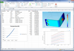
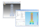
Multiphysics Simulation in Microsoft® Excel®LiveLink™ for Excel® is used for a parameterized high-power direct current COMSOL Multiphysics simulation of a bus bar. The parameters controlling the geometric dimensions as well as the applied voltage are edited in a Microsoft® Excel® spreadsheet and synchronized to the underlying model. A dedicated ribbon tab is added to Excel for easy access to parameters, variables, functions, geometry, mesh, solvers, and results.
|
|
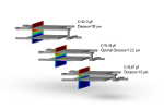
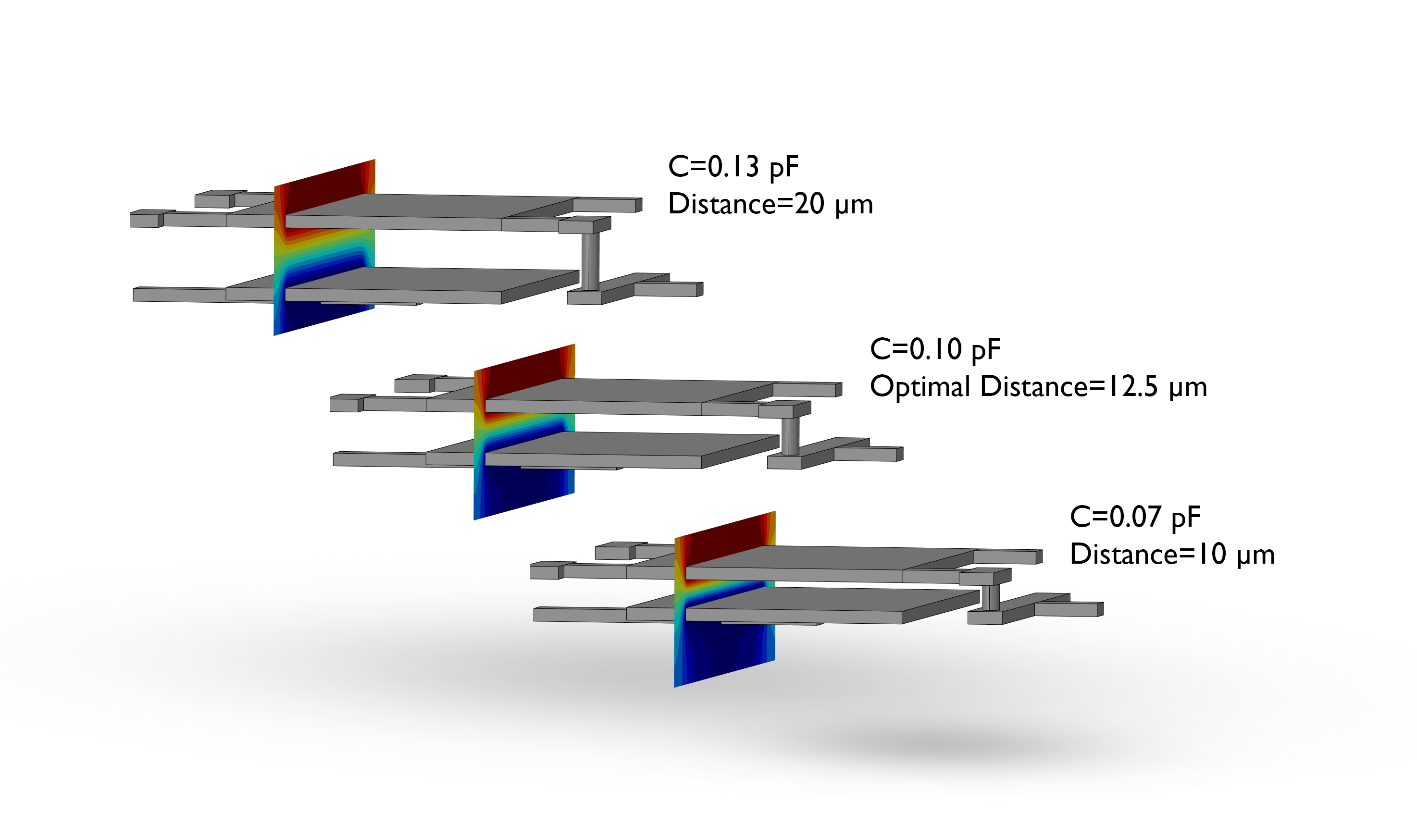
Parameter OptimizationTunable MEMS capacitors are used in tunable filters and tunable mobile antennas as found in multiple-band cell phones and other wireless devices. In this model a target capacitance of 0.1 pF is found by optimizing with respect to the distance between the capacitor plates. Three different configurations for different offset distances of the lower capacitor plate are shown. An optimal distance of 12.5 µm is computed.
|
|
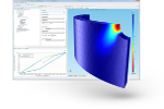
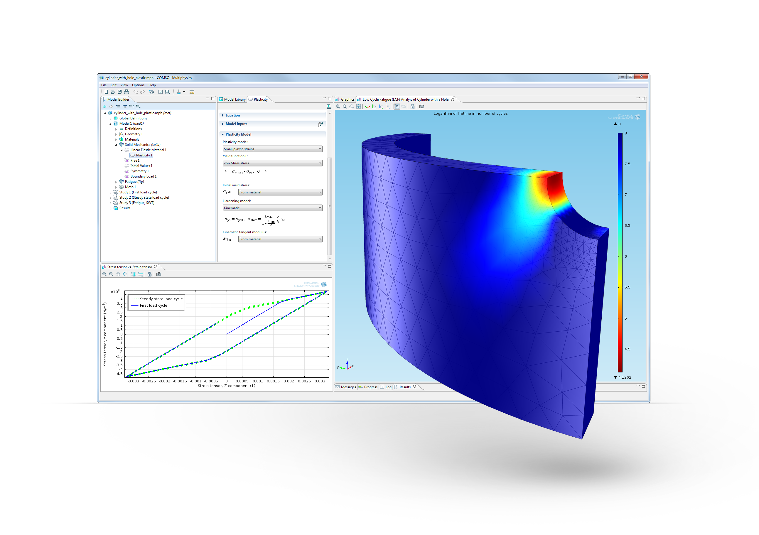
Fatigue Module Computes Structural Fatigue LifeLow cycle fatigue (LCF) analysis of a component subjected to multi-axial cyclic loading with an elastoplastic material model. In this solved and fully documented model from the COMSOL Model Library, different fatigue criteria are compared.
|
|
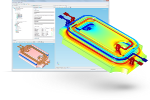
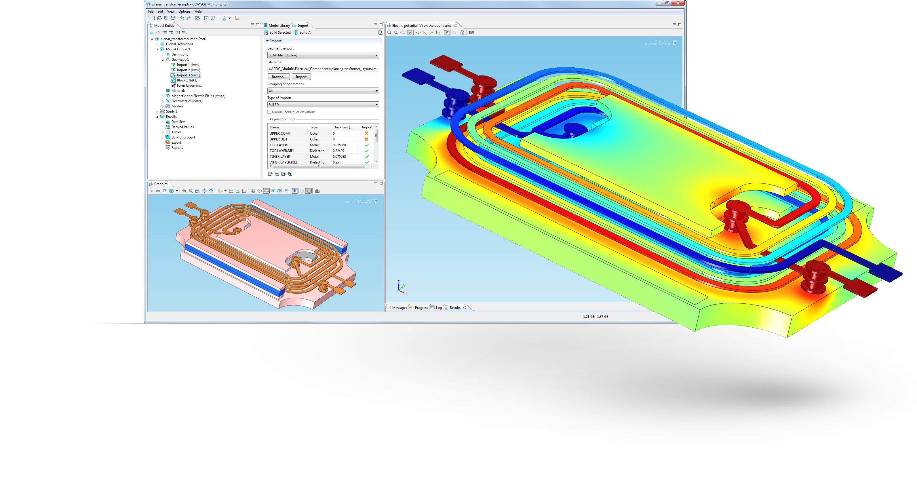
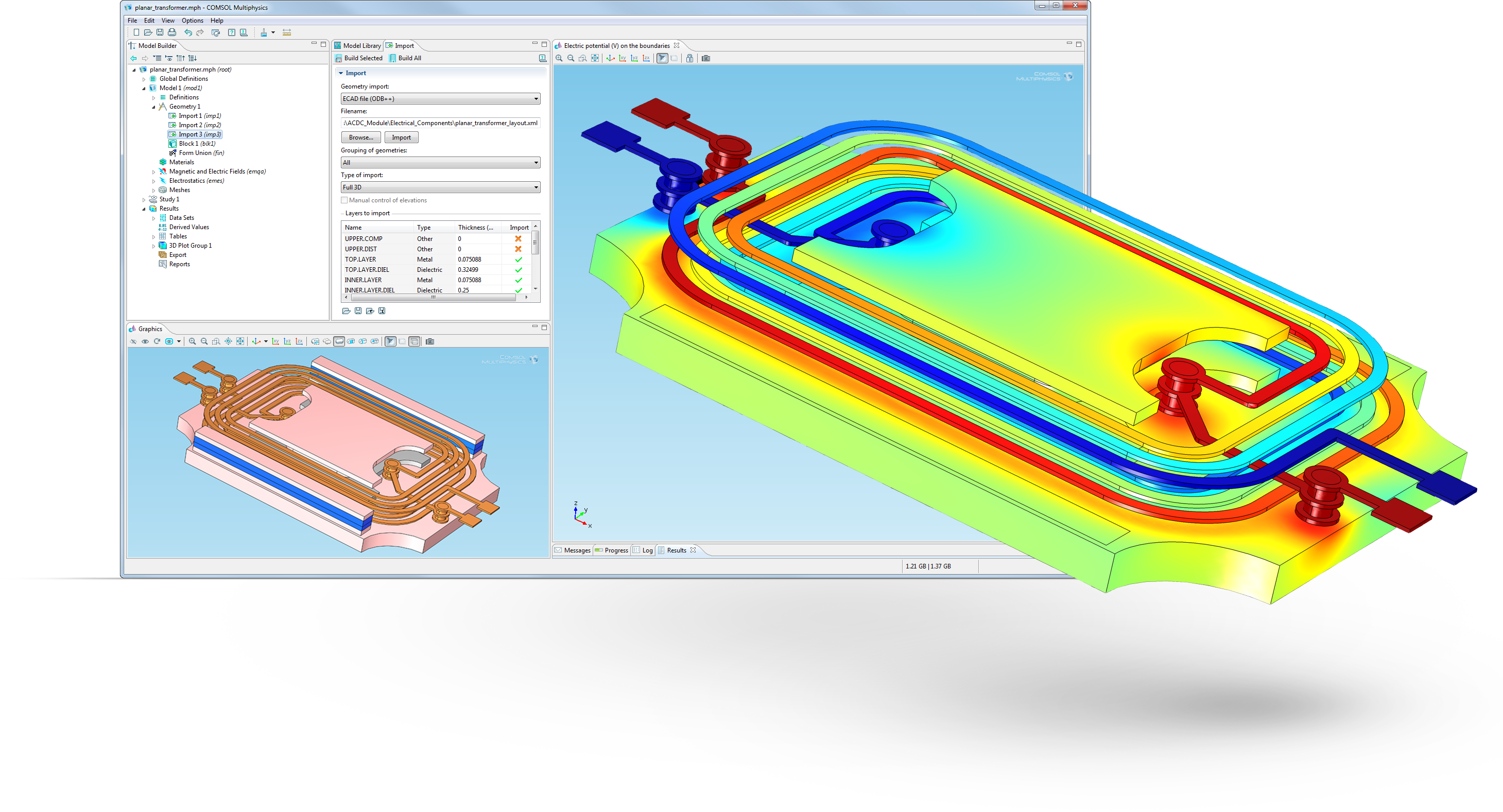
ECAD Import ModuleCapacitance and inductance extraction for a planar transformer model imported as an ECAD file. This type of device is used in power supplies and DC/DC converters where a slim high-power design is crucial. The entire layout, including the footprint of the transformer ferrite core, is imported from an ODB++(X) file. The ECAD Import Module is used to read the layout and automatically create a 3D geometry model in COMSOL Multiphysics of the Printed Circuit Board (PCB) and the ferrite core. The imported geometry is available in COMSOL where the users can run any simulation, for example, thermal and mechanical analysis.
|
|
LiveLink™ for Solid Edge®By establishing an integrated link, a change of a CAD design feature automatically updates the geometry in COMSOL Multiphysics, while retaining model settings. LiveLink for Solid Edge also provides the user with powerful repair and defeaturing tools for preparing the CAD model for simulation. |
|
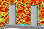
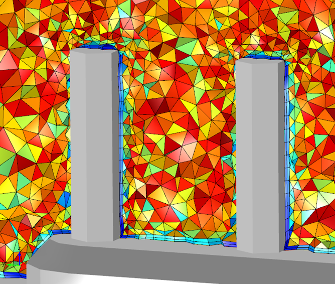
CFD Meshing ToolsThis picture shows the finite element mesh of a heat sink. The automatically applied boundary layer mesh with automatic corner refinement and new handling of sharp edges enable robust convergence of CFD and heat transfer simulations.
|
|
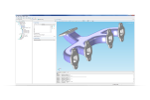
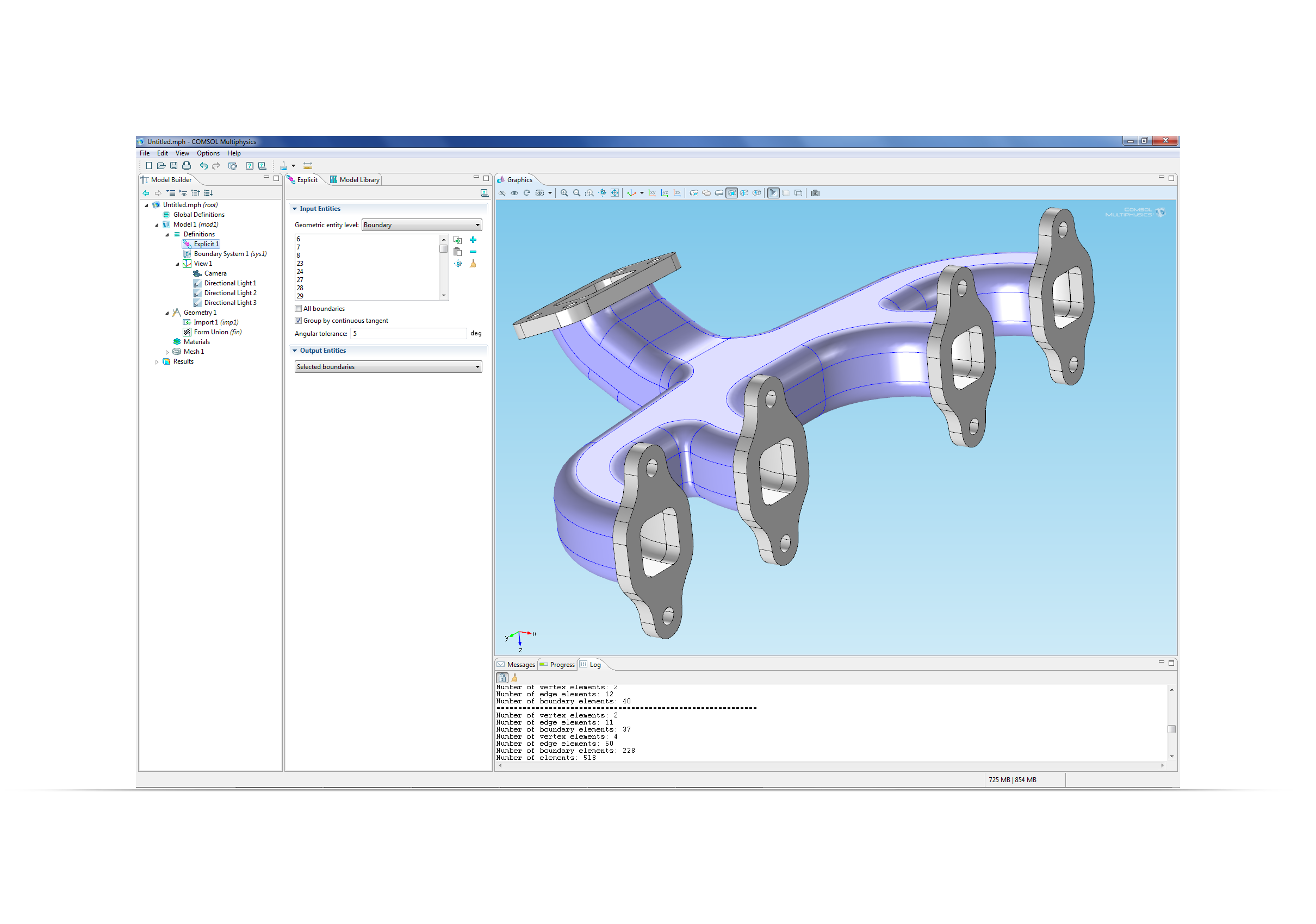
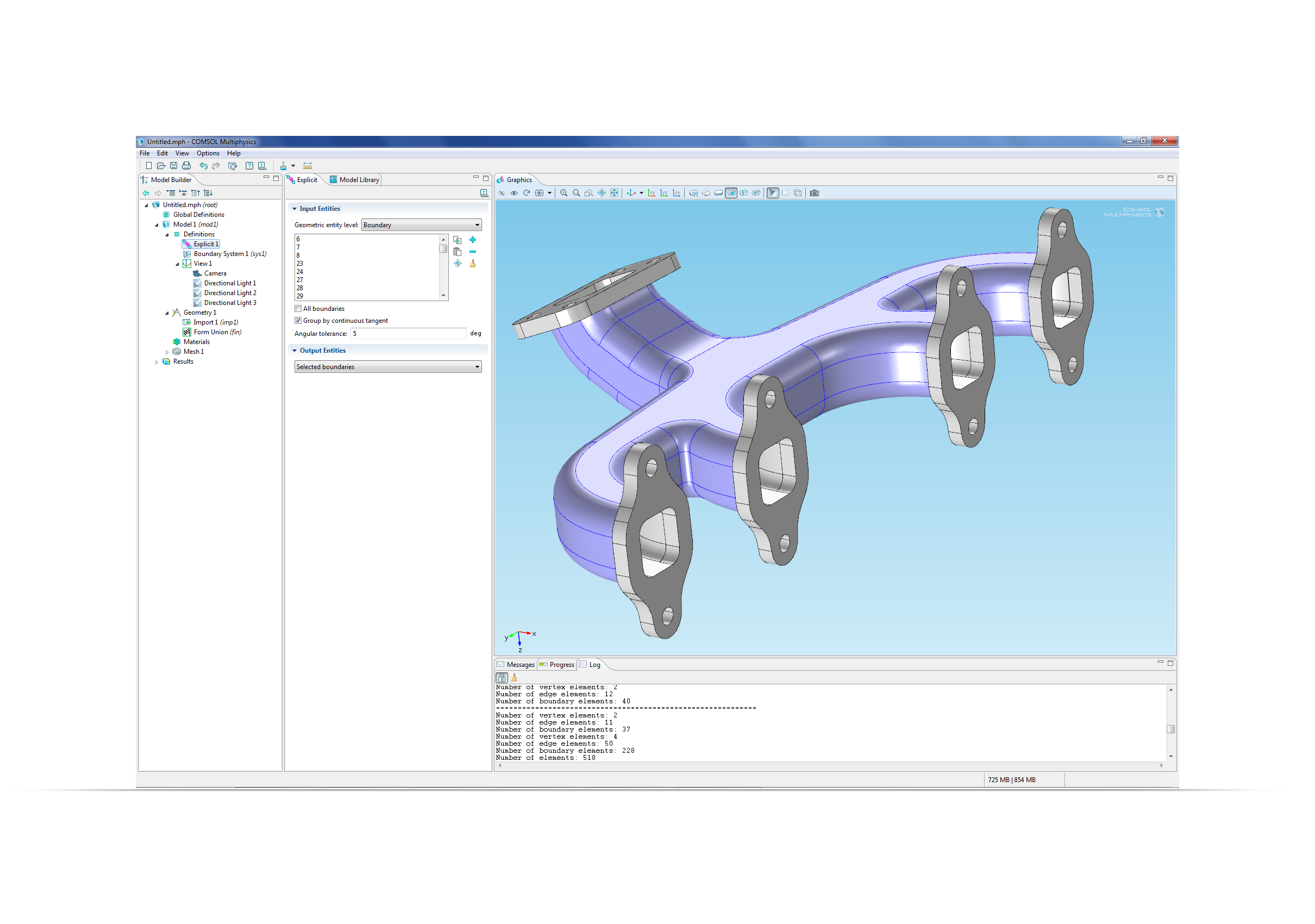
Geometry Selection ToolsSelection of boundaries in geometry models such as this exhaust manifold is made easier by the new continuous tangent selection. |