A Novel Type of Pattern Synthesis Implementation using Corrugated Apertures
The antenna pattern synthesis problem is of the utmost importance in almost every kind of antenna applications. Therefore, a very large number of contributions have appeared on this subject. A number of different implementation methods are well known, and widely used.
In this paper we present a new method that takes advantage of the antenna geometry to generate an aperture phase distribution that produces the desired pattern. The proposed antenna, for which the pattern is synthesized, is based on two existing design concepts, the choked horn [1] and the short backfire antenna [2]. It consists of a circular parallel plate excited in the center by a coaxial feed and a vertical circular corrugated flange. The antenna is omnidirectional in azimuth, and exhibits a low-sidelobe radiation pattern in elevation.
In the past, choke horns were used as feeds for reflector antennas. The chokes equalize the radiation patterns in the E-plane and H-plane to improve the symmetry and reduce the cross-polarization sidelobes [1]. Typically choke ring ground plane consists of several concentric thin walls, or rings, around the center where the antenna element is located. In addition to the small aperture, the full corrugated ground-plane has a significant role in determining the radiation patterns of the antenna. This is determined by the number of corrugations, their depth and periodicity.
By varying the depth of the corrugations, this mechanism can be used to manipulate the phase distribution on the aperture to generate a desired beam. For an omnidirectional antenna, to achieve a higher gain, the effective aperture in the elevation plane needs to be increased. The low profile of the parallel plate cannot alone excite the vertical aperture. This is why a sub-reflector similar to the one used in [2] was included. Figure 1 shows the profile that was optimized to generate the shaped beam pattern over a bandwidth of 10%.
In this case, due to the cylindrical symmetry associated with the geometry of the antenna, the Body of Revolution Method can be used. The computational effort involved is significantly smaller since the 3D problem becomes a 2D problem. COMSOL® software was used to optimize the radiation pattern using a shaped beam template mask. The average of the difference between the radiation pattern and the mask was used as goal function to minimize. Figure 1 shows the optimized geometry used in COMSOL® software to synthesize the omnidirectional Shaped beam antenna. The antenna is generated by sweeping the profile around the vertical axis 360.
The proposed antenna is the result of an optimization involving 20 variables (18 slot depths and 2 sub-reflector dimensions). The number of iterations required is about 300. Using FE of FDTD to solve the 3D full problem would require significant computational resources and would make the optimization process unrealistic. Even using two or four way symmetry the CPU time required by each iteration would be too much.
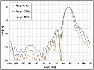
Figure 2 shows the elevation radiation patterns for three frequencies (14.4GHz, 14.9GHz and 154.GHz) and Figure 3 shows the comparison between the shaped beam antenna and the non-shaped-beam antenna (where all the corrugations are identical). A considerable reduction in the sidelobes level and an increase of about 2 dBi in gain is noticed.
Download
- herscovici_presentation.pdf - 2.18MB
- herscovici_abstract.pdf - 0.02MB