

Using geometry parts, created by you or added from any of the part libraries available with the COMSOL Multiphysics® software and some of its add-on modules, can greatly simplify and streamline the construction of more complex geometries for your simulations. Here, we show you how you can add and make use of geometry parts and create user-defined part libraries.
Geometry Parts and Part Instances
The CAD tools that are available for creating geometries with COMSOL Multiphysics include a number of so-called geometric primitives — basic geometric shapes such as blocks, cones, cylinders, spheres, pyramids, and tori in 3D. You can combine such geometric primitives to form more complex geometries for use in simulations.
Geometry parts provide a way to reproduce and parameterize such complex geometries. They can be used to simplify geometry creation by providing easy-to-use parts with a number of parameters for tailoring the part’s shape or dimension when added to a COMSOL Multiphysics geometry.
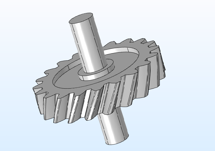
An example of a geometry part: A Helical Gear part from the Part Library available in the Multibody Dynamics Module.
When you add geometry parts (created directly in the model or taken from a Part Library), they become part instances in the active geometry, where they appear like any other geometry feature as part of the geometry sequence that defines the full geometry used for simulations. In the Settings window for geometry instances, you define the shape, dimension, and location of the part instance by specifying values of the input parameters that have been defined for the geometry part and the position and orientation of the instantiated part (relative to the global coordinate system or a user-defined work plane).
When you create a geometry part (under Global Definitions in the Model Builder), you have access to the same CAD features that are available in the geometry sequences that you use to define the geometries for model components: all of the geometric primitives; work planes with associated extrusions, rotations, and sweeps; and other geometry tools. For more advanced parts, you can also use programming by adding If, Else If, Else, and End If nodes in order to, for example, use some parameter to control certain aspects of the part. In addition, you can add Parameter Check nodes to issue an error if, for example, the user enters a parameter value that is out of range for a realistic part. You can define geometry parts for 1D, 2D, and 3D geometries.
For the parameterization, you can add input parameters for the geometry part directly in the Settings window for the main Part node. Those input parameters become available for the users of the part when they add it as a part instance. In addition, you can add a Local Parameters subnode to define additional parameters to be used locally within the part that do not need to be specified by the user.
Using Geometry Parts from a Part Library
Available Part Libraries
COMSOL Multiphysics and some of its add-on modules include part libraries with a number of geometry parts that are common and useful within each module’s application areas:
- COMSOL Multiphysics:
- Straight and bent (toroidal) pipes with walls
- AC/DC Module:
- Multiturn coils
- Single-conductor coils
- Magnetic cores
- Heat Transfer Module
- Various heat sinks
- Microfluidics Module:
- Various microfluidics channels
- Mixer Module:
- Various types of impellers
- Shafts
- Tanks
- Multibody Dynamics Module:
- External and internal gears
- Racks
- Ray Optics Module:
- Various types of lenses
- Mirrors
- Prisms
- Beam splitters
- Retroreflectors
- RF Module:
- Various types of connectors
- Surface mount devices
- Waveguides
- Structural Mechanics Module:
- Beams for different standards
- Various types of bolts
Documented Parts in the Part Libraries
For a few of the more complex parts, documentation is available as a PDF file. In those cases, the Open PDF Document button at the bottom of the Part Libraries window is available.
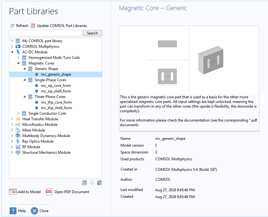
The mc_generic_shape geometry part, a magnetic core with a generic shape in the AC/DC Module, provides additional information through a PDF document.
Adding Geometry Parts from a Part Library
To choose a suitable geometry part, you can use the Search field at the top of the list of part libraries in the Part Libraries window to view a filtered set of parts. For all available part libraries, including any user-defined part libraries, you can search for text in the part descriptions and for contents in the geometry nodes that constitute the part.
You can add a geometry part from a Part Library to the existing list of parts in the model under Geometry Parts in the Global Definitions node. Right-click the Geometry Parts node and choose Part Libraries to open the Part Libraries window. From that window, choose a part and then click Add to Model in the lower-left corner of the Part Libraries window. The geometry part is added to any other existing geometry parts in the model under Geometry Parts, and you can then insert it as a part instance in any component geometry with a compatible space dimension. Contrary to user-defined parts, you cannot edit the part’s geometry when you add a predefined part from a Part Library.
Another way to add a geometry part from a Part Library is to add it as a part instance in a model geometry. Right-click the Geometry node in a 1D, 2D, or 3D model component and choose Part Libraries from the Parts submenu to open the Part Libraries window. From that window, choose a part and then click Add to Geometry in the lower-left corner of the Part Libraries window. You can only add geometry parts of the same space dimension as the model component.
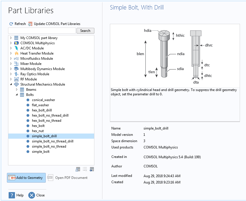
Click Add to Geometry to add the simple_bolt_drill part to the model geometry as a part instance for a parameterized simple bolt with a drill.
The geometry part is then added as a Part Instance node in the geometry sequence for the current model component.

The Simple Bolt, With Drill part added as a part instance in the geometry sequence. The Input Parameters section lists all parameters for this part.
Tip: To visualize curved and complex parts with a good resolution, select Fine from the Detail list under Visualization on the Graphics and Plot Windows page in the Preferences dialog box. This setting affects the rendering of the parts only; the underlying representation of the geometry is always exact.
Creating Parts and Adding a User-Defined Part Library
Parameterizing Parts
For geometry parts to be as versatile and useful as possible, they should be parameterized so that some parts of their shape and form as well as the dimensions of the part can be specified for each part instance. As mentioned above, you can define a number of input parameters that will be available to the user, and you can also add local parameters if the part requires some parameterization that is internal and should not be a user input. For a new part, think about which input parameters you need to add. Typical input parameters are geometric properties of the part, such as diameters, thicknesses, lengths, and angles.
An Example of a Geometry Part: A Cylinder with a Tapered End
As a simple example to illustrate the geometry part concepts, consider a part that consists of a straight cylinder with a tapered end. It could be some mechanical component, and the shape will resemble a crayon. Such a part consists of the following geometric primitives:
- Cylinder for the straight part
- Truncated cone (also called a conical frustum) for the top part
The following input parameters define the shape and size of this part:
- Base radius of the part
- Length of the straight cylinder
- Length of the tip (the truncated cone)
- Radius of the tip (the top radius of the truncated cone)
With this information, you can create this geometry part using these steps:
- Start a blank model
- Right-click the Global Definitions node and choose 3D Part from the Geometry Parts submenu
- In the Settings window for the 3D Part node, add the input parameters, as shown in the left screenshot below
- Right-click the Part node and add a Cone node for the tapered top and a Cylinder node for the base cylinder, and define their size and location using the parameters defined in the previous step (see the middle and right screenshots below)


The parameters used for the cylinder with a tapered end as a geometry part (left). The size, shape, and position for the base cylinder (middle) and top cone (right), defined using input parameters for the part.
These steps build the part as a cylinder with a tapered end. All defining properties are input parameters so that each part instance can be created with the desired size and shape. The local position of the top cone is shifted in the z direction with the length of the cylinder so that it always connects to the top of the cylinder.
You can now add this part as a part instance in a 3D component’s geometry. The following plots show three instances of this part with different sets of input parameters.


Three part instances using the part with the default parameter values (left), values for a thicker base (middle), and values for a thinner base and sharper tip (right).
Using Local Work Planes and Selections
There are a couple of additional options that you can use to make it easier to position the part instance in the resulting geometry and to define selections for adding materials and physics settings to the part instance. By adding work planes (as Work Plane nodes) to the part at some location, you can provide such planes for use as a “base plane” when positioning the part instance. You can select such work planes from the Work plane in part list in the Settings window for the part instance, instead of the default global xy-plane.
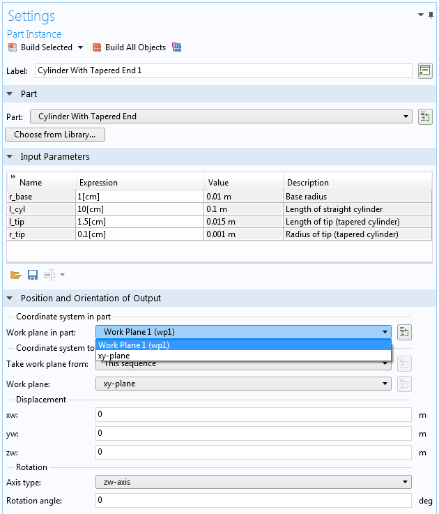
Selecting a user-defined work plane defined in the part as the baseline for the part instance’s position in the component’s geometry.
By defining selections in the part, you can, for example, make all domains or boundaries (or some specific subset of them) available as selections for materials, boundary conditions, and other physics settings. You can use the settings in the Selections of Resulting Entities sections in the contributing geometric primitives for a part to create selections based on the geometries of those primitives. You can also add user-defined selections as nodes in the geometry part (an Explicit Selection, for example), and then select the Keep selection check box and use On from the Show in instances list to make such a user-defined selection available in the part instance. In the Part Instance node’s Settings window, in the Domain Selections, Boundary Selections, or any other applicable selections section, select the check boxes under Keep to keep those selections in the component’s geometry. Also, select the check boxes under Physics to make the selections available when defining materials and physics for the component.
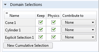
Domain selections for the Cone and Cylinder primitives as well as an explicit section are all made available for use in the component where the part instance is used.
Creating a User-Defined Part Library
If you define a number of useful parts, it is a good idea to collect them in a user-defined part library. A geometry part in a Part Library is a COMSOL Multiphysics MPH-file that contains the part only. When saving the geometry part to an MPH-file, choose a suitable title, description, and thumbnail that give a good description of the part when it goes into a Part Library.
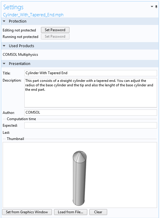
The Settings window for the geometry part, where you can define a title and provide a description and a thumbnail image.
Save the part file to a folder with a suitable name that will become the name of your user-defined part library. Then, add that directory from the Part Libraries window by clicking the Add User Part Library button underneath the list of part libraries and then browsing to the desired folder.
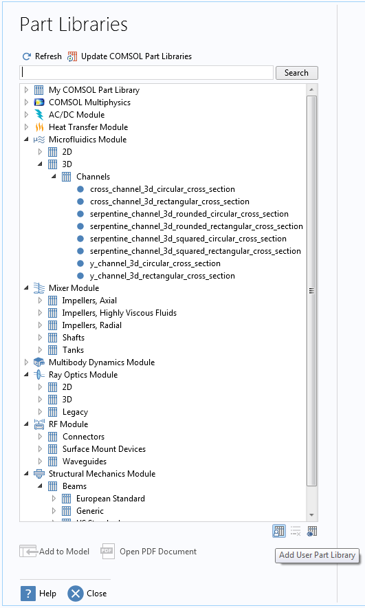
The Add User Part Library button.
The user-defined part library is then added to the list of part libraries, and you can choose from all of the parts that are available as MPH-files in the corresponding folder on the file system. The following screenshot shows the Cylinder With Tapered End part added to the user-defined part library called My COMSOL Part Library.
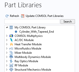
A user-defined part library with an available part has been added to the Part Libraries window.
To add a PDF document with additional information for a geometry part in a user-defined part library, create a PDF file with the desired information and store it in the folder for the user-defined part library with the exact same name as the corresponding MPH-file. The Open PDF Document button then becomes available when you select that part from the library.
Other Parts of the Geometry Tools in COMSOL Multiphysics®
In this blog post, we have taken an in-depth look at geometry parts and part instances, the available part libraries, and how to create user-defined parts and part libraries. There are many other parts of the CAD and geometry tools and features available in COMSOL Multiphysics that you can use, perhaps together with geometry parts, to create the geometries that you want for your simulation projects. Take a look at the following resources for more information:
- Watch videos on creating geometries in the COMSOL Learning Center
- Learn more about geometries on the COMSOL Blog:

Comments (0)