

In rapid thermal annealing, a process step in producing semiconductors, measuring the temperature of a wafer is key. Without accurate measurements, overheating and nonuniform temperature distributions may occur, both of which impact the effectiveness of the process. This is why tools like the COMSOL Multiphysics® software give you the ability to analyze temperature distributions within an RTA design. From these results, you can better assess the performance of the sensor component and optimize its configuration to achieve accurate measurements.
A Brief Introduction to Rapid Thermal Annealing
For those in the semiconductor industry, rapid thermal processing (RTP) is recognized as an important step in producing semiconductors. In this manufacturing process, silicon wafers are heated to temperatures greater than 1000°C in a few seconds or less. This is often achieved by using high-intensity lasers or lamps as heat sources. The temperature of the wafer is then slowly reduced in order to prevent any dislocations or water breakage that could occur as a result of thermal shock. The applications for RTP range from activating dopants to chemical vapor deposition, a topic that we’ve discussed previously on the blog.
Rapid thermal annealing (RTA) is a subset of RTP. This process involves rapidly heating an individual wafer from ambient temperature to somewhere in the range of 1000 to 1500 K. For RTA to be effective, there are a few considerations that need to be made. For one, the step must occur quickly; otherwise, the dopants can be diffused too much. Also important to the step’s success is preventing overheating and nonuniform temperature distributions. This facilitates the need for accurate measurements of the wafer’s temperature during RTA, which are typically achieved using either thermocouples or IR sensors.
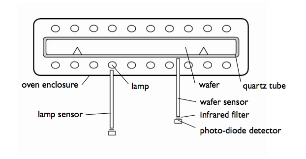
A schematic of a common RTA apparatus.
An IR sensor, when ideally positioned, only receives radiation that is reflected and emitted by the silicon wafer. This is otherwise known as secondary radiation. Other desirable characteristics of sensors include short response times and high levels of accuracy. To design an optimal IR sensor, you could perform a parameter optimization in COMSOL Multiphysics. But before that step, and what we’ll focus on here, is using simulation to determine if an IR sensor is the more appropriate choice for an RTA configuration when compared to the inexpensive thermocouple.
Analyze Temperature Distributions and Sensor Performance in an RTA Configuration
As highlighted in the diagram above, RTA often makes use of double-sided heating in many applications. In such a setup, IR lamps are placed above and below the silicon wafer. For our Rapid Thermal Annealing tutorial, we chose to model a single-sided heating apparatus.
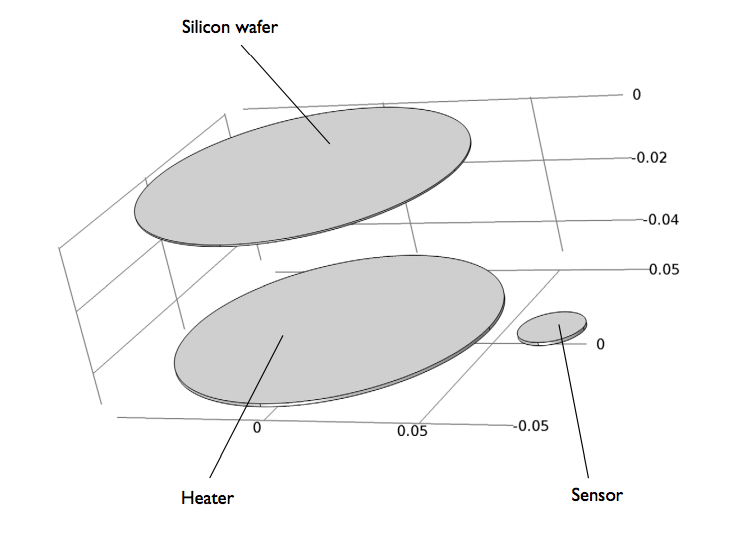
The model geometry for the RTA configuration.
In the above figure, the components are stored in a chamber featuring temperature-controlled walls with a set point of 400 K. The geometry of the chamber walls are thus omitted, as this results in a closed cavity. The model further assumes that radiation and convection cooling dominate the physical system. A heat transfer coefficient is used to model the convective cooling of the wafer and sensor to the gas.
The lamp, meanwhile, is treated as a solid object that has a volume heat source of 25 kW. Insulation is included on all sides of the object, except for the top surface. It is through this top surface, which faces the wafer, that the heat leaves the lamp as radiation. The model uses a low heat capacity for the solid to capture its transient start-up time. The other thermal properties of the lamp are the same as those of copper metal.
Let’s begin by looking at the temperature distribution in the lamp, wafer, and sensor after 10 seconds of heating. As the simulation plot shows, there is a significant difference between the temperature of the wafer, which is around 1800 K, and the temperature of the sensor, which is around 1100 K. You may also notice that there is an uneven temperature distribution in the wafer. While not included in our example model, reconfiguring the heat source could help address this issue.
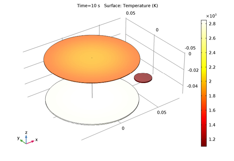
The transient temperature field after ten seconds of heating.
We also want to see how well the temperature of the sensor reflects that of the wafer’s surface. For this purpose, it is helpful to plot the temperature transient of the centerpoint on the wafer’s surface facing the lamp along with the temperature at a certain point on the top surface of the sensor. In the plot below, these two measurements are denoted by Twafer and Tsensor, respectively. The temperature transient of the lamp (Tlamp) and the irradiation power at the surface of the sensor Isensor are also shown.
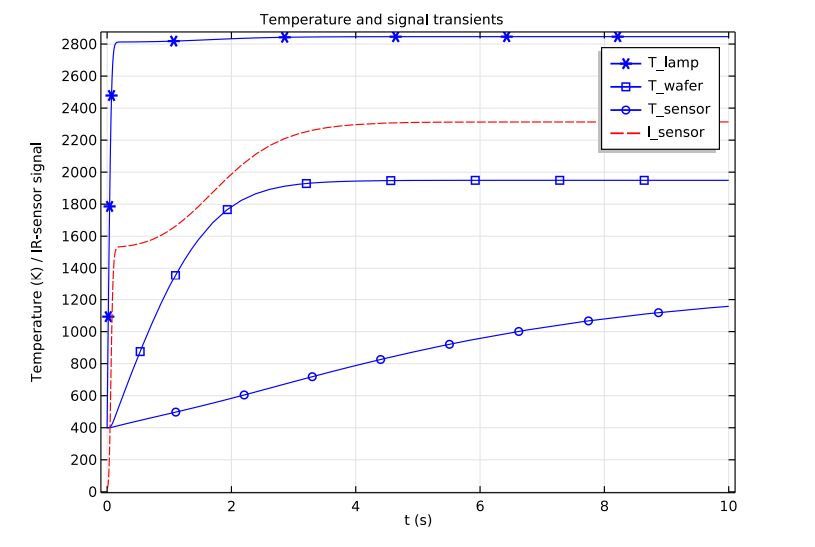
Comparison of the temperature transients for the individual components of the RTA configuration along with the irradiation power at the sensor’s surface.
As the results indicate, the temperature of the sensor poorly reflects that of the wafer. A thermocouple’s signal would therefore not be very useful in regulating this process. But the IR detector does show good agreement with the characteristics of the wafer temperature. Such accurate measurements of the wafer’s temperature are achieved with a scalar amplification.
There are some drawbacks to IR sensors that are important to mention as well. For instance, the IR sensor has far less inertia than the wafer. While the wafer needs some time to heat up, the sensor detects the radiation as soon as it starts. Further, an IR signal depends on the wafer’s emissivity. Because the emissivity varies with temperature, the response is nonlinear. The signal is also rather sensitive to changes within the geometry. With tools like COMSOL Multiphysics, you can fully study such phenomena and gain a better understanding of how to optimize your RTA configuration for successful semiconductor manufacturing.
Explore Further Uses of Simulation in the Semiconductor Industry
- Read about more applications of simulation in the semiconductor industry on the COMSOL Blog:

Comments (0)