

When working with both SolidWorks® and COMSOL Multiphysics® via LiveLink™ for SolidWorks®, you can choose to synchronize selections. Here’s why you should and how to do it.
Why Synchronize Selections Between SolidWorks® and COMSOL Multiphysics®?
Relying on selections for model set-up can help speed up the process of assigning material properties, boundary conditions, and other model settings. We can easily reuse selections for various settings. When adding or removing entities from the selection list, all Model Builder nodes that use the selection will be updated automatically. By relying on selections in the geometry sequence, we can also easily track, for example, a set of boundaries or domains that originate from a certain geometry operation. Up until recently, the latter functionality has been available only with geometries drawn in COMSOL Multiphysics, but with the latest release of LiveLink™ for SolidWorks®, you can also apply this technique when synchronizing geometries between SolidWorks® and COMSOL Multiphysics®.
There are two ways you can work with selections using the LiveLink program. First, if you have assigned materials for the components or bodies (in a multibody part) in your SolidWorks design, the selections for these are automatically synchronized to the COMSOL Multiphysics model. Second, you can set up your own selections using the COMSOL Selections window in SolidWorks®. Selections you define this way can include geometric entities, such as faces or edges, but also CAD assembly components or features from the model tree of the CAD model. For features, the selection includes the output of the feature, which is usually a set of faces or solid bodies.
To understand how to synchronize selections, let’s take a look at a couple of modeling examples.
Selections for Material Settings
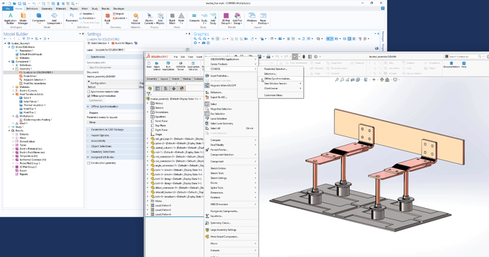
Consider this CAD model of a Small Outline Integrated Circuit (SOIC) and a cut-out of a circuit board below it:
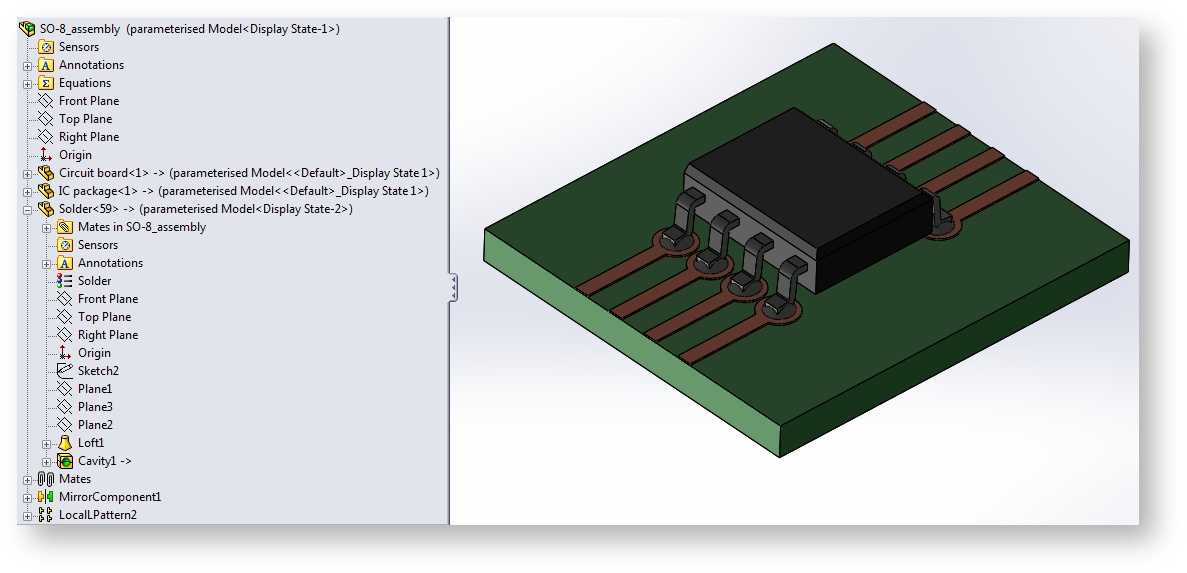
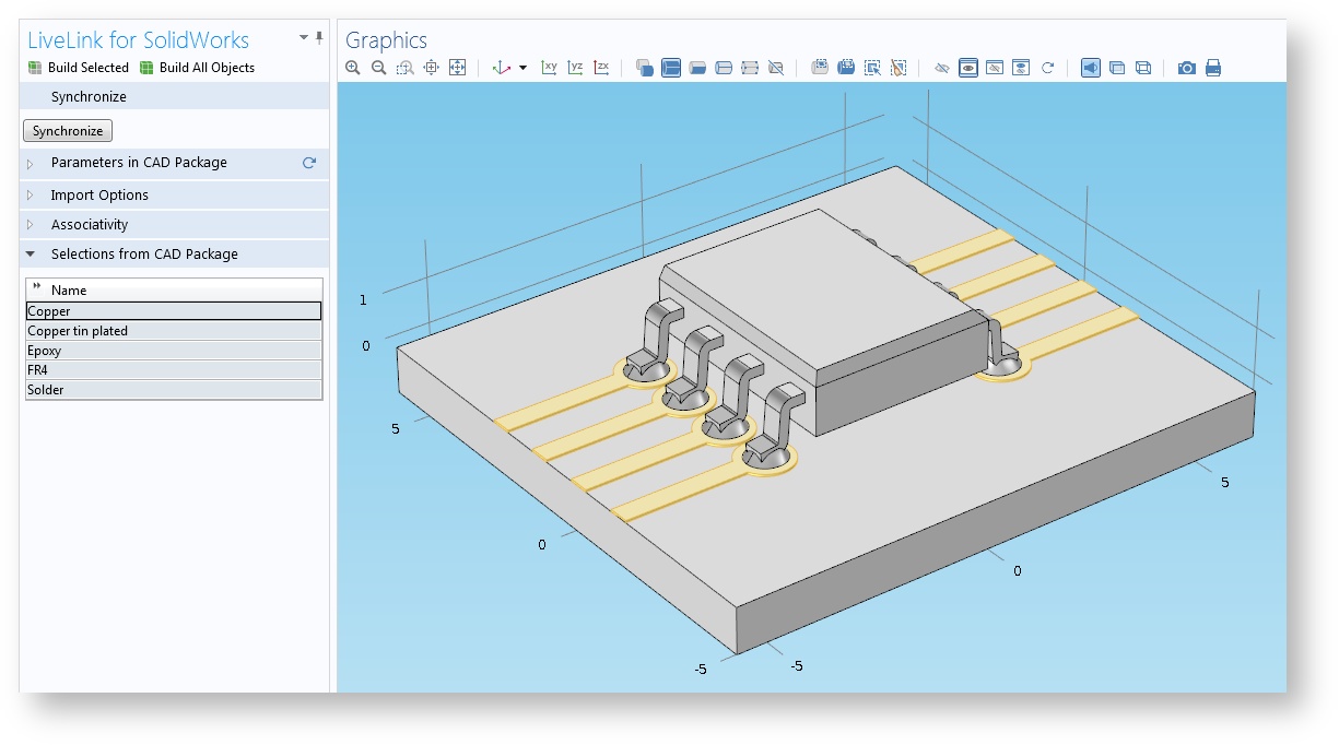
The SolidWorks assembly consists of three parts, which in turn are composed of multiple solid bodies. Materials have been defined both on the part level and for the solid bodies in the parts. After synchronization between SolidWorks® and COMSOL Multiphysics®, selections are automatically created according to the material definitions in the assembly. We can inspect the selections by expanding the “Selections from CAD Package” section of the LiveLink settings window in COMSOL Multiphysics.
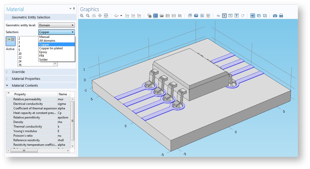
To assign a material for the copper traces highlighted in the image above, we can use the “Selection” drop-down list available in the Materials settings window. A Selection drop-down list appears in all the places where a domain selection can be made.
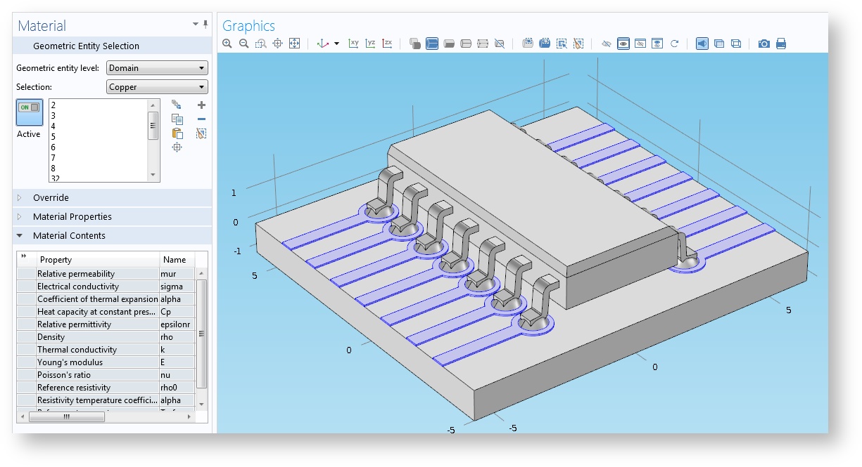
The material selections not only save us time when setting up a simulation, but also enable us to run parametric sweeps even if new solid objects are introduced into the geometry. Consider, for instance, that we would like to change the parameter that controls the number of pins for the IC package. The assembly has been set up to generate new solid bodies for the new lead and copper traces, and these automatically receive the correct material assignments in SolidWorks.
After synchronization with COMSOL Multiphysics, the selections are updated to include the newly created solids. Material settings or other settings that use the material selections are automatically updated in the model.
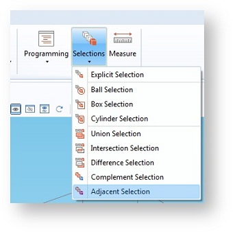
Note that the synchronized material selections are always available on the domain level in the COMSOL model. We can, however, quite easily select the boundaries adjacent to a domain selection by adding the Adjacent Selection operation to the geometry sequence downstream of the LiveLink node.
User-Defined Selections
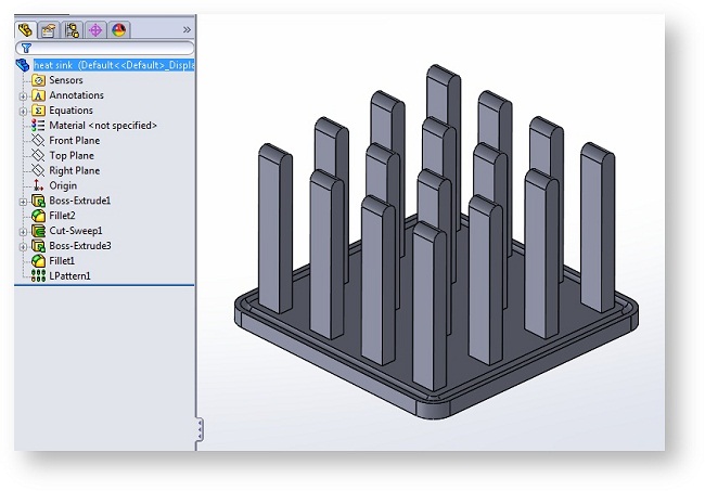
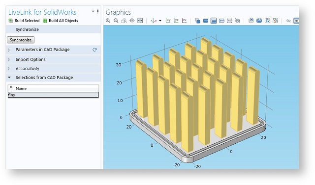
Let’s take a look at an example of a simple heat sink design in SolidWorks®.
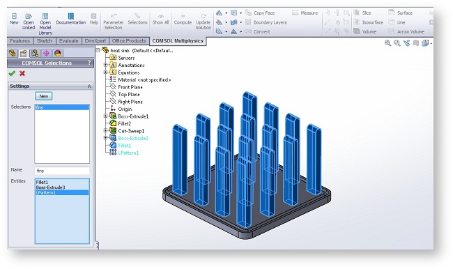
Using the Selections button from the COMSOL Multiphysics® tab in SolidWorks®, we can select the three features whose outputs are the faces of the fins of the heat sink.
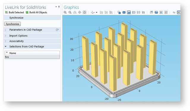
After synchronizing the geometry with COMSOL Multiphysics, the selection with the name “fins” appears in the LiveLink settings window:
The automatically synchronized selection can save many clicks when setting up a boundary condition on the heat sink fins. We can also track the new faces introduced into the geometry when we increase the number of fins in the SolidWorks model. Since the selection in SolidWorks is defined by the features that create the fins, the selection in the COMSOL model automatically includes the new faces as the design changes.
Further Reading
- Learn more about what you can do with LiveLink™ for SolidWorks®
SolidWorks is a registered trademark of Dassault Systèmes SolidWorks Corp.


Comments (0)