

Cars come with either an automatic gearbox or a manually operated one, a stick shift. With a manual gearbox, we use the stick shifter very frequently while driving the car, yet we hardly ever think about the way the mechanism works. Here, we investigate how it works and what forces are acting on it when submitted to a very common load case — selecting first gear — with the help of a COMSOL Multibody Dynamics model of the gearshift mechanism.
Restoring a Classic Car
The restoration of a classic car triggered me to do some research on how a gearshift works. When designing a car with a manual gearbox, the sensible thing to do is to place the gearshift lever directly on top of the gearbox, with the stick poking through the floor and/or the central console. However, in the past, sometimes it was considered convenient to have the gearshift lever attached to the steering column. That made it possible to seat three people in the front, on a bench.
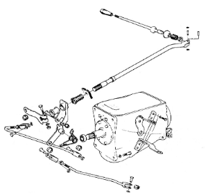
There are some challenges with a steering column-mounted gear shifter, though. With the gearshift mounted far away from the device it is supposed to operate, the question is how to get the motion from the lever down to the gearbox. The solution involves a lot of connecting rods and hinges. The classic car being restored, a Volvo 121, had such a steering column-mounted gear shifter.
How did it survive 50 years of wear-and-tear? How large are the forces acting on the individual components when you switch gear?
Modeling the Gearshift Mechanism Using COMSOL Software
In order to answer these questions, we turned to the Multibody Dynamics Module, which provides predefined features for creating the different types of joints between components, and the Structural Mechanics Module. The Multibody Dynamics Module enables you to model mechanical assemblies, by expanding on the capabilities of COMSOL Multiphysics and the Structural Mechanics Module.
To simulate the behavior, we created a model using ball, cylindrical, hinge joints, and contact surfaces. The mechanism components were chosen to all be of the deformable kind, meaning we used structural mechanics to calculate the deformations of the individual parts. Alternatively, some or all parts could have been modeled as rigid. Finally, as a loading sequence, the stick shifter was moved backwards and upwards in two steps in order to simulate shifting the gearbox into first gear.
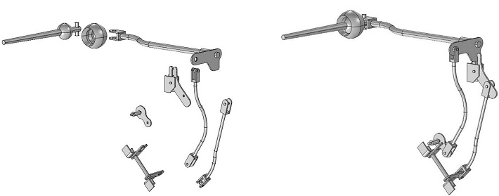
Geometry of the gearshift mechanism, made with a series of flexible linkages. Individual components are shown on the left, and the full assembly on the right.
Flexible Multibody Analysis
To investigate the movement, the kinematics, of the gear shifter mechanism, we performed a transient analysis. Shifting into gear took 2 seconds, an appropriate and leisurely pace for a car of that age.
We were particularly interested in finding out what the magnitude of the forces were on the individual components during motion. Large contact forces may point to excessive wear. As it turned out, none of the hinges or linkages were subjected to excessive loading, the order of magnitude was only a few Newton at most, as can be seen in the example below for one of the hinges.
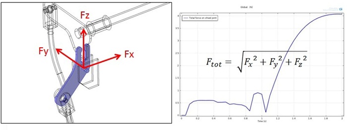
Global plot of the joint force over time.
Further Reading
- Download the Gear Shift Level Model from the Model Gallery
- Check out our archived webinar on Multibody Dynamics Simulation
- Explore the Multibody Dynamics Module


Comments (0)