

Importing meshes into COMSOL Multiphysics is often necessary when interfacing between different programs. With COMSOL Multiphysics version 5.0, these meshes can be converted into solid geometry objects for further investigation and modeling capabilities. You can also perform boolean operations on the new geometry for CFD, electromagetics, and acoustics applications.
Advantages of the Create Geometry from Mesh Feature
There are multiple options for importing meshes into COMSOL Multiphysics software for users that interface with specialized mesh programs. The mesh formats supported by COMSOL software include NASTRAN® Bulk Data, VRML v1, and STL. Building upon this practice, users of COMSOL Multiphysics version 5.0 now have the option to do more with these imported meshes.
The Create Geometry from Mesh feature adds an additional Component to your model with the geometry included, created from the imported mesh. With this new feature, you can create a surrounding domain around this geometry, as shown in the video further down the page. After creating this separate domain, perform boolean operations such as Difference, Intersection, and Union. If the original geometry is to be meshed as well, the new Copy feature for meshes comes in handy. No need to re-mesh the original geometry — simply copy the mesh from the original Component into the new one.
Note that, for the time being, this can only be done when there are no intersections between the geometry objects.
There are a few applications that come to mind when introducing this modeling technique. The surrounding domain could be the fluid surrounding a solid object or the air surrounding an electromagnetic or acoustics device. For the electromagetic and acoustic examples, this comes in handy when using Infinite Elements (AC/DC Module) and Perfectly Matched Layers (RF, Wave Optics, Acoustics Modules). When modeling these applications, there needs to be a domain between the geometry and the Infinite Elements/Perfectly Matched Layer domains.
Here is a short list of the possible applications and associated physical phenomena involved:
- CFD — Fluid-structure interactions
- Electromagnetics — E-field and B-field in the surrounding media
- Acoustics — Sound pressure level and acoustic pressure field in the surrounding media
- Your own application
Video Tutorial: How to Create a Geometry from a Mesh
Video Transcription
In this video, we will show you how to create a geometry from an imported mesh.
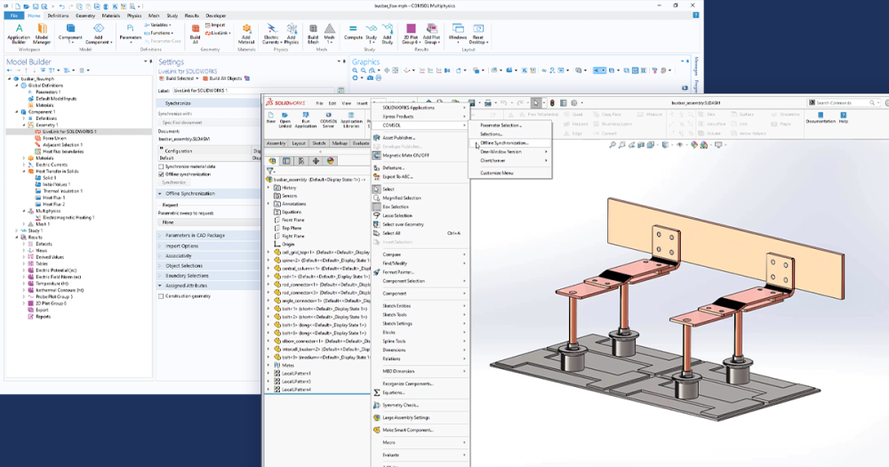
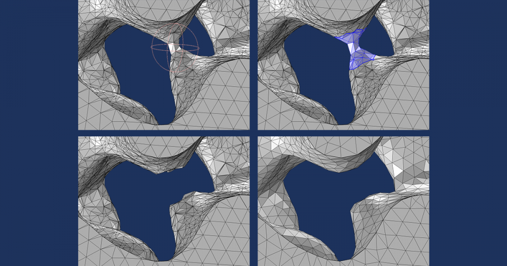
So, let’s get started. Here, we have COMSOL Multiphysics open and our mesh already imported, which we want to finalize. And then we go under the Mesh ribbon and click the “Create Geometry from Mesh” button to add the feature. You’ll see after adding this feature, a new component was added along with a new geometry, which we can see in the settings window, is Mesh 1 from our first component. Click “Build Selected”, and now we are going to want to convert this geometry into a solid. So we go under the Geometry ribbon, and under Conversions, select “Convert to Solid”. Click the object and click “Build Selected”.
Now, we are going to create a block, which will completely surround our imported mesh geometry, as well as lie within the center of the block. Click “Build Selected”, and you’ll see our block has been generated.
Now, if we turn on the Transparency, we can see our imported mesh geometry lying within the center of the block. And what we’re going to do is subtract this imported mesh geometry from the geometry of the block. To do this, we go back again to the Geometry ribbon, and under Booleans and Partitions select “Difference”. Click the block as the object to add and the imported mesh geometry as the object to subtract. Click “Build Selected” and our new geometry has been created.
Now, we can go to the Mesh ribbon, and selecting “Mesh 2”, we can now click “Build Mesh” to generate the mesh. So, here, the meshing for our finalized geometry has been created.
Now, let’s go under the Results ribbon and create a Mesh data set for the second mesh. Change the label to reflect the mesh being used, which is Mesh 2, as well as the mesh selected. Now we can turn off the Transparency, and create a 3D Plot Group, which will house our Mesh plot for the second mesh. So, again, we change the label to reflect the mesh being shown, the Level to Volume, the Element color to Gray, and then we enable an Element Filter, to show the elements located in the x-direction at a position greater than 25. Now we can click “Plot”, and we can see that we’ve successfully subtracted our imported mesh geometry from the geometry of the block.
This concludes our tutorial on how to create a geometry from an imported mesh.

Comments (0)